OXYGEN-NET
Note
This is an optional feature and requires a license.
OXYGEN-NET enables the combination of multiple DEWE3 systems within the same Ethernet network into a single high-channel-count measurement system. These systems can be synchronized and controlled using one or more Master units.
Each system in an OXYGEN-NET setup must have a unique hostname. For example, if you are using multiple DEWE3-A4 systems, name them DEWE3-A4-1, DEWE3-A4-2, and so on. The hostnames can be changed in the Windows settings (see Fig. 631) under Control panel → All Control Panel Items → System → Computer name.
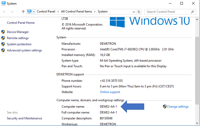
Fig. 631 Changing the hostname
Terminology
This glossary defines key terms used in this chapter:
Acquisition master: The superordinate master responsible for coordinating the synchronized acquisition start across all nodes.
Master unit: A device that claims and controls slave units. It queries data from Slave units. Multiple devices can act as Master units in an OXYGEN-NET system, but a Master unit cannot simultaneously function as a slave unit.
Master group: A group of Master units that share the same recording ID.
Measurement unit: A DEWETRON device that can perform measurements and be integrated into an OXYGEN-NET system.
Multi-Master system: An OXYGEN-NET system where one or more Slave units are claimed by multiple (>1) Master units.
Recording group: A group of devices that share the same recording group ID and follow the same recording commands.
Single-master system: An OXYGEN-NET system where one or more Slave units are claimed by a single Master unit.
Slave unit: A DEWETRON measurement device claimed and controlled by a Master unit. It sends data to the Master unit. Several devices can be configured as Slave units in an OXYGEN-NET system.
Synchronization master: A device that serves as the source clock for the synchronization signal in an OXYGEN-NET system.
OXYGEN-NET topologies
Every OXYGEN-NET system consists of at least one Slave unit and one Master unit, but can also include multiple Slave units and multiple Master units. Both a Slave and a Master can either be a measurement device (e.g. any DEWE3 device) or a standalone PC. This flexibility allows for various system topologies. In general, an OXYGEN-NET system topology consists of two main components: a network topology for data transfer and system control and a synchronization topology for signal synchronization. In case only a single measurement device is used no synchronization network is required, and only a network topology exists. However, when multiple measurement devices are involved, both a network and synchronization topology are required.
This chapter provides examples of various OXYGEN-NET topologies, separating network and synchronization topologies for better clarity and understanding.
Network topologies
The following examples show different possibilities for network topologies supported by OYXGEN-NET, including both Single-Master and Multi-Master systems. Although Master units are depicted as external PCs in the following illustrations, keep in mind that DEWETRON devices may also be used as Master units.
Single-master system
Fig. 632 illustrates a topology where one external PC serves as the Master unit, and three Measurement Nodes function as Slave units.

Fig. 632 Network topology with a single Master unit and three Slave units
Multi-Master System
Fig. 633 displays a topology where multiple external PCs serve as Master units and three Measurement Nodes acting as Slave units. All Units share the same ethernet network.

Fig. 633 Network topology with multiple Master and multiple Slave units.
Since DEWE3 devices are equipped with at least two Ethernet ports, a dual-LAN network can be implemented. Fig. 634 demonstrates an example setup with two Master units and three Slave units, where each Master has its own independent network.
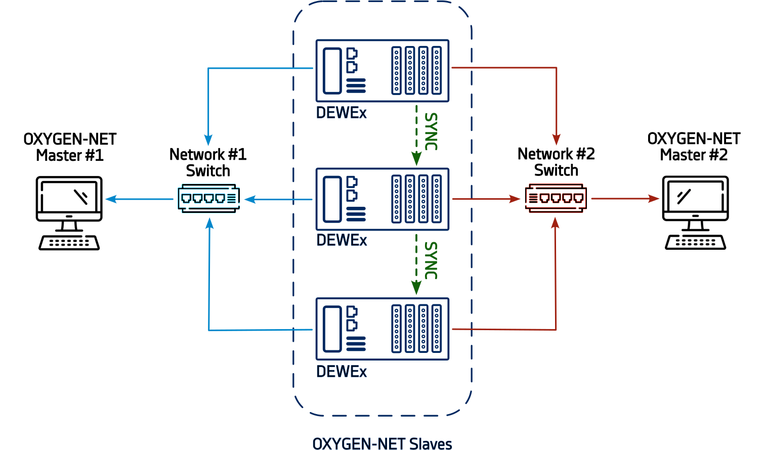
Fig. 634 Multi-Master system based on two different networks
Note
The illustrated network switches are optional. In case the Master unit supports enough ports for all Slave units no switch is required.
Synchronization topologies
All DEWETRON devices feature an internal Enclosure Sync, which can be transmitted via the TRION-SYNC-BUS. Additional DEWETRON provides multiple hardware options for signal synchronization across multiple systems, including the DEWE3 Chassis Controller, TRION-BASE module, TRION-TIMING module, and TRION-VGPS module. These hardware options enable the usage of further time codes such as IRIG, GPS, and others.
The following figures illustrate supported synchronization topologies. The primary difference between these topologies is how measurement nodes are synchronized and whether they are connected to an external synchronization source.
Internal TRION-SYNC
Fig. 635 shows a synchronization topology using the TRION-SYNC-BUS, based on the internal Enclosure Sync signal of any DEWE3 device. This is the default synchronization method for all DEWE3 devices within an OXYGEN-NET. The system operates in a free-running mode without an external synchronization source, with all nodes connected via TRION-SYNC-BUS. This option is recommended when absolute timestamping is not required and no synchronization with third-party systems is needed.

Fig. 635 Synchronization topology using the left DEWE3 device as the synchronization source, with the signal distributed via TRION-SYNC-BUS
External SYNC signal
This synchronization topology relies on an external third-party system as a reference clock, distributing the synchronization signal to each measurement node individually. It is recommended for widely distributed systems, where distances exceed the limits of the TRION-SYNC-BUS, or when a wired connection is impractical.
Since the TRION-SYNC-BUS is not used in this setup, each measurement node must be equipped with the appropriate hardware to receive the external synchronization signal. Fig. 636 illustrates a potential application of this topology.

Fig. 636 Synchronization topology where each measurement node receives an external synchronization signal individually
Mixed external SYNC signal distributed via TRION-SYNC
This synchronization topology combines both internal TRION-SYNC and external SYNC signal methods. In this setup, an external synchronization signal is received by one DEWE3 device. Based on the received signals timebase a synchronization signal is distributed to all other DEWE3 devices via the TRION-SYNC-BUS.
The enclosure that receives the external sync signal automatically becomes the Synchronization Master and must be equipped with the appropriate hardware. This topology is ideal when synchronization to an absolute timestamp is required.

Fig. 637 Mixed synchronization topology, where an external sync signal is received by one DEWE3 device and distributed to other devices via TRION-SYNC-BUS
OXYGEN-NET topology including TRIONet3
The TRIONet3 is a front-end device, therefore it does not create an OXYGEN-NET network when connected to another device. Integrating it into an existing OXYGEN-NET system does not alter the network topology. Instead, the TRIONet3 functions as an extension of the connected device, with both acting as a unified measurement node. However, the TRIONet3 still requires both a network and a synchronization connection. Fig. 638 illustrates two example topologies incorporating TRIONet3 devices.

Fig. 638 OXYGEN-NET topology examples including TRIONet3s
OXYGEN-NET - Menu overview
The OXYGEN-NET menu is split up in three different sections: Nodes, Sync and Settings.
OXYGEN-NET Menu – Nodes
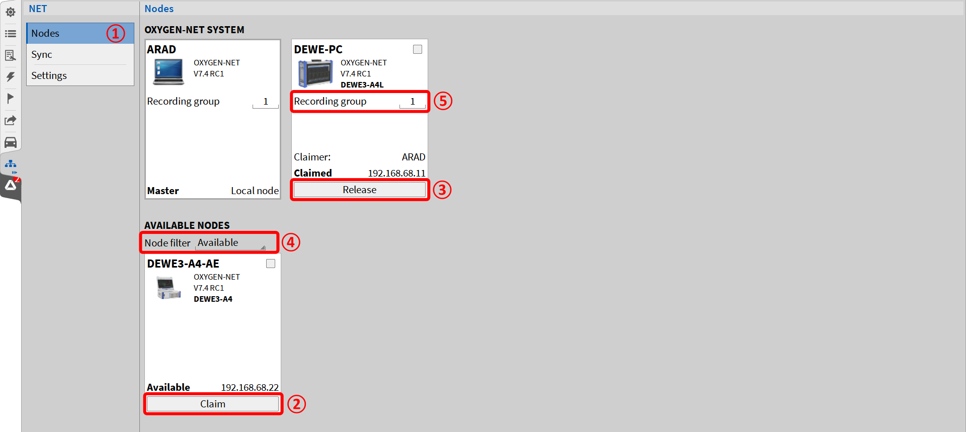
Fig. 639 OXYGEN-NET menu – Nodes
The Nodes menu (see ① Fig. 639) provides an overview of all measurement devices connected to the same Ethernet network. The section AVAILABLE NODES displays all available devices, while the section OXYGEN-NET SYSTEM shows all Slave Units connected to this Master Unit.
To create or extend an OXYGEN-NET network, the Enable OXYGEN-NET option must be active on every device involved. Additionally, to allow a device to be claimed, the Allow claim option must be enabled. To enable and disable these options, refer to OXYGEN-NET Menu – Settings. Devices with Enable OXYGEN-NET and Allow claim active can be claimed by a Master Unit and connected to the OXYGEN-NET system. To claim a device, click the Claim button below the respective measurement device or select multiple devices via the tick box and click any Claim button (see ② in Fig. 639). Once claimed these devices are regarded as Slave Units.
Claimed devices can be released from the OXYGEN-NET system by clicking on the respective Release button (see ③ in Fig. 639). After releasing the measurement device, it can be used as a standalone device again or connected to another OXYGEN-NET system.
Node Filters
The Node filter (see ④ in Fig. 639) allows users to sort available measurement devices based on their status:
Available: Displays devices on the network that are unclaimed and ready to be claimed.
Claimed: Displays devices that have already been claimed by any Master Unit.
All: Displays all devices connected to the Ethernet network, regardless of their claim status.
Recording Groups
The Recording Group input field (see ⑤ in Fig. 639) allows users to set a Recording Group ID. All devices with the same ID form a Recording Group, which shares all recording commands (start, pause, stop). This enables actions such as starting a recording on one Master Unit and stopping it on another.
All Master devices in a Recording Group receive identical data from a slave unit. By default, the recorded data is stored locally on each device within the group. Devices assigned to different Recording Groups operate independently. Recording IDs can be assigned to both master and slave devices, with numbers ranging from 0 to 999. Below are different examples based on an OXYGEN-NET Multi-Master system involving two Master Units and one Slave Unit:
Case: Identical ID on All Devices
Master 1: Recording ID 1
Master 2: Recording ID 1
Slave: Recording ID 1
In this setup, a recording command affects all three devices, and identical data is stored locally on each by default.
Case: Different ID on All Devices
Master 1: Recording ID 1
Master 2: Recording ID 2
Slave: Recording ID 3
Here, recording commands only affect the device with the matching ID. For example: A recording started on Master 1 must also be stopped on Master 1, and data is stored only on that device. A recording started on Master 2 functions independently. The Slave Unit with its own unique ID, cannot initiate or control recordings.
Case: Mixed IDs
Master 1: Recording ID 1
Master 2: Recording ID 2
Slave: Recording ID 1
In this scenario, a recording command issued on Master 1 will also affect the Slave Unit, resulting in identical data being stored on both devices. Master 2, with a different ID, operates independently.
OXYGEN-NET Menu – Sync
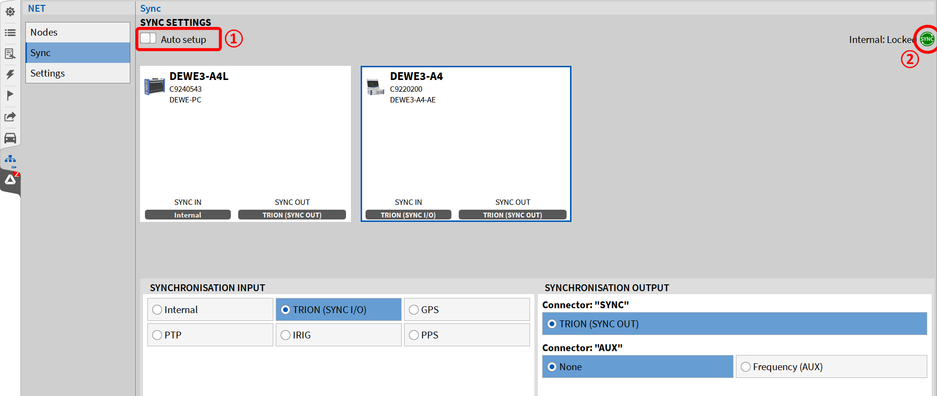
Fig. 640 OXYGEN-NET menu – Sync
Auto Setup Slider
The Auto Setup slider (see ① in Fig. 640) allows users to enable or disable automatic synchronization setup:
Enabled: Synchronization is automatically configured by the DEWE3 enclosure. The synchronization is set to TRION-SYNC-BUS, and no manual settings can be changed while Auto Setup is active. If the Master device lacks measurement hardware (e.g., Notebook or PC), the first claimed Slave is automatically set as the Sync Master. By default, the Sync Master uses its internal time base as SYNCHRONIZATION INPUT.
Disabled: Users can manually configure synchronization input and output settings. For more details, refer to Sync settings.
Sync Status Indicator
The Sync Status Indicator (see ② in Fig. 640) displays the current synchronization status of the system:
Red: No valid synchronization signal is connected.
Orange: A valid synchronization signal is connected, but the system is not yet locked (this may take a few seconds and will lock automatically).
Green: A valid synchronization signal is connected, and the system is locked.
Grey: The synchronization signal is based on the system’s internal clock.
The Sync Status Indicator is also available in the Action Bar when the Sync Setup window is closed (see ② in Fig. 14). For additional details, refer to the Troubleshooting section.
OXYGEN-NET Menu – Settings
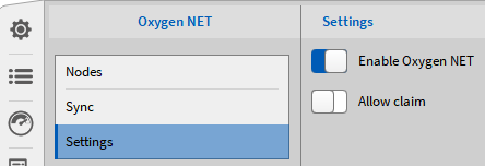
Fig. 641 OXYGEN-NET menu – Settings
In the Settings menu, the user can enable or disable the OXYGEN-NET functionality and select whether the measurement device is claimable or not.
If OXYGEN-NET is disabled, the measurement device can neither be used as a Master nor Slave Unit in an OXYGEN-NET system. Thus, the device is not visible to other users in the Nodes menu of other DEWE3 systems (see OXYGEN-NET Menu – Nodes). If OXYGEN-NET is enabled, the device can be used within OXYGEN-NET systems and is listed in the Nodes menu of other DEWE3 systems.
If Allow claim is enabled, the measurement device can either be used as a Master unit or be claimed by another device and used as a Slave unit. If Allow claim is disabled, the measurement device can only be used as a Master unit (and claim other devices) but not as a Slave unit. Fig. 642 illustrates this in OXYGEN, where Allow claim is disabled for the device DEWE-PC and enabled for DEWE3-A4-AE.
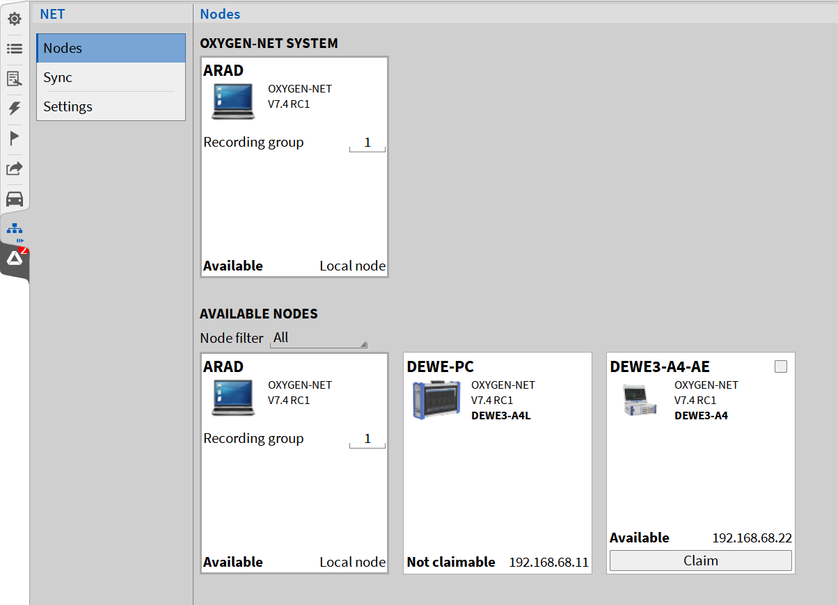
Fig. 642 Visibility varieties
The device DEWE3-A4-AE illustrates visibility for other users if OXYGEN-NET is enabled and Allow Claim is enabled. The device DEWE-PC illustrates visibility for other users if OXYGEN-NET is enabled and Allow Claim is disabled.
Setting up an OXYGEN-NET System
The following steps describe the procedure for configuring several devices to an OXYGEN-NET system. A detailed description of the following settings and properties is provided in OXYGEN-NET - Menu overview. Possible hardware connection schemes can be found in OXYGEN-NET topologies.
Generic setup
Connect all measurement devices that shall be used within the OXYGEN-NET system to the same ethernet network. Make sure that the IP addresses of all measurement devices are within the same subnet mask. If DHCP is enabled and no DHCP server is available, devices will default to the operating system fallback range (169.x.x.x).
Start OXYGEN on all measurement devices and Enable OXYGEN-NET in the OXYGEN-NET menu Settings on all devices.
Select Allow claim on the devices that shall be configured as slaves. Without enabling Allow claim, Slave Units cannot be claimed by Master Units.
Go to the OXYGEN-NET menu Nodes on the Master Unit. Based on the selected node filter, measurement device(s) will appear in the Available Nodes section. To claim a device, click the Claim button below the respective measurement device or select multiple devices via the tick box and click any Claim button.
Note
If a device should not be listed in the Available Nodes section though expected, refer Troubleshooting.
After claiming a device by the Master unit, it is listed in the OXYGEN-NET System section of the OXYGEN-NET menu Nodes. A claimed device functions as a Slave Unit and is controlled by its claiming Master Units. The first Master Unit to claim a measurement node is designated as the Claimer and performs the role of the Acquisition Master, responsible for coordinating the synchronized acquisition start across all nodes. A Slave Unit may be released from the OXYGEN-NET system again by clicking on the Release button.
After claiming a device, the screen of the Slave Unit will be locked, and the information* Claimed by X* will be displayed in the lower right corner of the software

Fig. 643 Claimed information on the Slave device. In this case, the Master device is named CAIRHIEN
Synchronization setup
SYNC-Setup using the internal TRION-SYNC
To synchronize measurement devices using only the TRION-SYNC-BUS, first, connect all devices using SYNC cables. Plug one end into the SYNC OUT connector of the Synchronization Master and the other into the SYNC IN connector of the next measurement unit. This daisy-chain setup allows the sync signal to be distributed across multiple devices (see Fig. 644). Note that synchronization cannot be transmitted via an Ethernet router—it must be directly wired between devices.
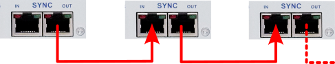
Fig. 644 Sync wiring of multiple measurement units using the TRION-SYNC-BUS
Next, configure the OXYGEN-NET Sync settings. The simplest approach is to enable Auto Setup, which automatically applies the correct synchronization settings. If manual configuration is required, follow these steps:
Go to the OXYGEN-NET menu Sync and disable Auto setup.
Select the measurement unit serving as Synchronization Master. In the SYNCHRONIZATION INPUT section select Internal. In the SYNCHRONIZATION OUTPUT section select TRION (SYNC OUT) for connector: “SYNC”, and None for all other connectors.
For all other measurement Units select TRION (SYNC I/O) as input and TRION (SYNC OUT) as output. Set None for all other output connectors.
A green background color of the SYNC indicator on all devices will display that the sync wiring is correct and synchronization is completed. All Slave units are now synchronized to the relative time base of the Master unit and a measurement may be started by clicking the Record button on the Master unit.
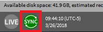
Fig. 645 Correct sync wiring
Note
If the background color of the SYNC indicator is orange, the sync wiring is incorrect. For further information, refer to Troubleshooting.
SYNC-Setup using an external synchronization signal
When using an external signal for system synchronization, the setup differs slightly.
First, ensure that each DEWE3 device has the appropriate hardware installed to receive the external signal. Then, connect the external synchronization source (e.g., GPS antenna, IRIG grandmaster clock, or PTP signal). It is not required to use the same synchronization source for every node—for example, one node may use GPS while another uses PTP.
Next, open the OXYGEN-NET Sync menu and disable Auto setup. Manually configure the SYNCHRONIZATION INPUT and SYNCHRONIZATION OUTPUT settings based on the external signal source and supported hardware. Once properly configured, the SYNC indicator on all devices will turn green, confirming successful synchronization. Fig. 646 illustrates an example where one device receives an IRIG signal from an external source, and another device synchronizes via TRION-SYNC.
For troubleshooting synchronization issues, refer to Troubleshooting.
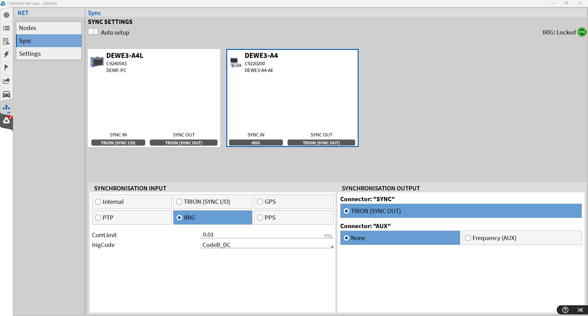
Fig. 646 Example SYNC configuration using an external IRIG source
Setup generation on an OXYGEN-NET system
Data transfer and storage
In the channel list, the user can decide on various data transfer and storage settings for every single channel via the columns
Active: the slider marked with an orange arrow in Fig. 647 will activate or deactivate the data acquisition from a channel
Stored: the red button marked with a green arrow in Fig. 647 will enable the storing of the data
Trans.: the green button marked with a blue arrow in Fig. 647 will enable the data transfer from the Slave unit to the Master unit.
Note
It is not possible to transfer data from the Master Unit to a Slave Unit nor between Slave Units but only from the Slave Units to the Master Unit.
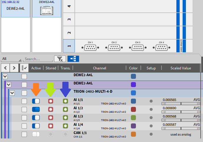
Fig. 647 Slave unit channels visible in the Master units’ Channel List
Fig. 648 shows the following possible combinations:
Channel A1/1 will only be acquired but not stored or transferred. Data may only be used for math calculations on the Slave unit.
Channel A1/2 will be stored on the Slave unit but not on the Master unit
Channel A1/3 will be transferred to the Master unit but neither stored on the Slave unit nor on the Master unit. The channel may only be used for math calculations on the Slave unit or the Master unit.
Channel A1/4 will be transferred to the Master unit and stored both on the Slave unit and the Master unit.
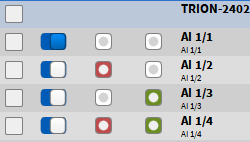
Fig. 648 Channel transfer and recording combinations
How to store data on a Master Unit without storing it on a Slave Unit
To prevent data from being stored on a Slave Unit, assign the Slave Unit a different Recording Group ID than the Master Unit. This results in no recording taking place on the Slave Unit and consequently, no data being saved on it.
Save & load setup
When a setup is saved on a Master Unit, the configuration of any connected Slave Units (including channel settings, measurement screen configurations, etc.) is included in the setup file stored on the Master Unit. No separate setup file is saved on the Slave Units automatically.
When loading a setup file on a Master Unit that includes an OXYGEN-NET configuration, OXYGEN attempts to automatically claim the required Slave Units during the setup load process. If the Slave unit cannot be claimed, the hardware mismatch dialog will appear (see Fig. 22).
Note
OXYGEN must already be running on the Slave Units when loading a setup on a Master Unit, as it does not start automatically when the setup is loaded.
Save & load setup for a Multi-Master System
In a Multi-Master system, successfully loading a setup on one Master Unit will overwrite the current setup on any connected Slave Units and update shared settings across all connected Master Units. To simplify working with multiple Master Units and minimize the risk of errors we suggest the following workflow:
Create a general setup file for an OXYGEN-NET system on one Master Unit.
Copy this file to all other Master Units.
Load the copied file on each Master Unit.
After successfully loading the setup files, perform any further adjustments.
Recording data with an OXYGEN-NET system
OXYGEN-NET systems support the same recording options as an individual system does. However, due to the possibilities of Multi-Master systems and multiple Recording Groups various recording behaviors arise. In the following, we will discuss potential recording behaviors within an OXYGEN-NET system.
Recording Groups
All devices with the same Recording Group ID form a Recording Group. All devices within the same recording group share their recording commands: start recording, pause recording, and stop recording. Meaning if any of these actions are performed on any device within a Recording Group, every device within the Recording Group will follow this command. For examples cases see paragraph Recording Groups in section OXYGEN-NET Menu – Nodes.
Manual recording
After pressing the Record button on any Master Unit within the same Recording Group, a recording is started on every device within the Recording Group of the Master Unit. The same applies to pausing and stopping recordings. All devices with the identical Recording ID will follow the command. For details about Recording Groups as well as example cases see section OXYGEN-NET Menu – Nodes.
Note
In Multi-Master systems, recording is blocked as soon as a master device has opened the Data Channels menu. Further, as soon as one Master Unit exits the Data Channel menu, every other Master Unit also exits the Data Channel menu.
After stopping a recording, the measurement will be stored the following way in general:
Any Master Unit stores all transferred data plus data acquired by the Master Unit itself (if available) locally.
Any Slave Unit stores its respective data locally. One Slave Unit does not store any data from different slave units.
Note
Data transfer and storage settings (see Data transfer and storage) significantly influence the finally stored measurement files.
Triggered recording
Triggered recording is supported for OXYGEN-NET systems. The OXYGEN-NET system takes into account all trigger events defined on any Master Unit. This enables flexible trigger setups, but also a high susceptibility to errors for ill-considered trigger events. Individual trigger settings on a slave device are ignored.
User-reduced statistics recording is supported (see Triggered Events). The user-reduced statistics data are not transferred from the Slave units to the Master unit to avoid an increase in the data to be transferred. They are calculated on the Master unit for the Slave unit channels that are transferred to the Master unit.
Multi-File recording
OXYGEN-NET systems support Multi-File Recording. When enabled on a Master Unit, the setting also applies to data files stored locally on Slave Units. For seamless recording, it is recommended to use identical Multi-File configurations across all Master Units with the same Recording ID. Any Multi-File settings configured on a Slave Unit will be ignored.
Additional Information
Typical data transfer rates (80 MB/s):
16 bit: up to 350 channels @ 100 kHz
24 bit: up to 350 channels @ 50 kHz
The Master unit can either be a measurement unit with TRION hardware or a laptop without TRION hardware. If a laptop without TRION hardware is used as Master Unit, the first Slave unit claimed by the Master unit is defined as Sync master.
The sync wiring can be done before OXYGEN is started or when OXYGEN is already running.
The setup on the Slave units must be roughly prepared before claiming them, only existing channels can be configured from the master.
If the hard disk of the Master unit is full, the recording will stop automatically on the Master unit and on all Slave units.
If the hard disk of a Slave unit is full, the recording will only stop on the affected Slave unit but not on the other devices.
If the software mode of the Master unit is switched to PLAY mode, because a data file is opened, the Slave units are released from the Master unit. To avoid such scenario, use OXYGEN Viewer.
The Node names are the operating systems host names. These can be edited in e.g. Windows under System → Info → Change PC Name.
ORION DAQ/DSA hardware is not supported with OXYGEN-NET.
Troubleshooting
General troubleshooting
Device(s) not listed in the Available nodes
If a device is not listed in the Available Nodes section as expected, make sure that
The Node filter is set to All or Available
OXYGEN-NET is enabled on the missing measurement device
The network connection is working
The IP address of the missing measurement device is within the same subnet range
Sync issues
If the sync wiring is incorrect, the background color of the SYNC indicator will be orange and the message Waiting for sync will be displayed in the lower right corner of the software (see Fig. 649). If this appears, make sure that the sync wiring is correct. For further information, refer to OXYGEN-NET menu – Sync and Fig. 644.

Fig. 649 Incorrect sync wiring
If the sync wire is disconnected during the measurement, a Sync Lost marker is added to the Event List and the message Waiting for sync will be displayed in the lower right corner of the software. The background color of the SYNC indicator will become orange.

Fig. 650 Software feedback if sync signal is lost during the measurement
The recording will be continued until the Stop button is pressed. Be aware that the recording will not be time synchronous any more without valid sync connection.
A reconnection of the sync wire will not help to resync data during recording. The measurement must be stopped before data is time synchronous again.
If the sync wire is reconnected during the measurement, the SYNC indicator will become red and the message Invalid synchronization signal will be displayed in the lower right corner of the software.

Fig. 651 Software feedback if sync signal is reconnected during the measurement
If the system is configured in a way, that is a not allowed topology, there is the following error message next to the SYNC indicator within the Sync settings: No valid sync setup found for node XY.

Fig. 652 Error message displaying a measurement node with an invalid sync setup
If there is a problem, that at least one node cannot be synchronized, there is an error message saying: Out of Sync. In this case check each measurement node individually.
Slave loses network connection
If a slave device loses the network connection during the measurement, the master device adds a Node Lost marker to the Event List and displays the message Slave Node Lost:… in the lower right corner of the software (see Fig. 653).
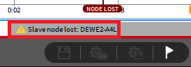
Fig. 653 Software feedback on master device if slave node loses network connection
The affected slave device adds a Node Lost marker to the Event List and opens a Master Lost pop-up menu (see Fig. 654).
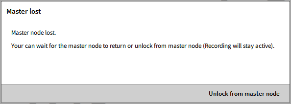
Fig. 654 Software feedback on slave device if slave node loses network connection
If the user selects Unlock from master node, the recording will be continued until the Stop button is pressed and the slave device can be used as standalone unit.
If the network connection is fixed in the meantime, the pop-up window on the slave device will close again and the slave device can be controlled by the master device again. Data recording is still synchronous, because the sync connection was still active. A Node found marker will be added to the Event List.
The measurement on potential other slave devices is not affected and they do not realize that a slave node was lost.
Master Unit loses network connection
If the master device loses the network connection during the measurement, the master device adds a Node Lost marker to the Event List and displays the message Slave Node Lost:… in the lower right corner of the software (see Fig. 653).
All slave devices add a Node Lost marker to the Event List and open a Master Lost pop-up menu (see Fig. 654).
If the user selects Unlock from master node, the recording will be continued until the Stop button is pressed and the slave devices can be used as standalone units.
If the network connection is fixed in the meantime, the pop-up window on the slave device will close again and the slave devices can be controlled by the master device again. Data recording is still synchronous, because the sync connection was still active. A Node found marker will be added to the Event List.
Devices are not found (same subnet mask on two ports)
When assigning static IP addresses, ensure that the same subnet mask is used for both the master and slave. When using multiple network connections, it is recommended that each connection be assigned its own subnet mask. For example, port 1 with 192.168.100.1 and port with 192.168.0.1.
Multi-Master-specific troubleshooting
Loading setups simultaneously
It is NOT recommended to load setups simultaneously within an OXYGEN-NET system. Loading setups on multiple master clients at the same time may cause extended waiting times and potential issues when determining an acquisition master. To avoid errors, load setups sequentially, one master client at a time.
Losing system devices
This section addresses scenarios involving the unintentional disconnection of any device from an OXYGEN-NET system, which could result from a network disconnection, device crash, power loss, or similar issues.
Losing system devices during recording
If a system device is lost during an active recording, a full system software restart is recommended once the recording has stopped. A full restart involves:
Releasing all nodes on every master client
Closing and reopening OXYGEN on each master and slave device,
Reloading the existing OXYGEN setups on every device.
Losing system devices during non-recording
If a device is lost while the system is not recording or armed, the response depends on the type of device lost:
If the acquisition master is lost: All master devices will release their measurement nodes. A full system software restart, as described above, is recommended.
If any master client (other than the acquisition master) is lost: The affected master will release its claimed slaves, but the overall system will remain unaffected. Restarting OXYGEN on the affected device should resolve the issue. If issues persist, perform a full system software restart.
If any measurement node is lost: Each master device that had the node claimed will release it and display a notification: “Slave node lost: Slave_X.” A full system software restart is recommended in this case.
Limitations of OXYGEN-NET
No data transfer between different Slave units or from Master unit to Slave unit. Data can only be transferred from Slave units to Master units.