OXYGEN setup
The OXYGEN Setup menu contains all settings which affect software settings and will be stored in the registry. These settings are saved per default and do not have to be saved in a setup file.
The content of the individual submenus will be explained in the following sections in detail.
General settings
Storing and File name
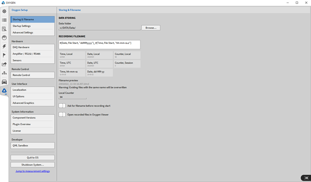
Fig. 142 System settings - overview
Data storing: The folder to which data shall be stored, a prefix for data-filename and a folder to which data shall be exported can be specified here.
Recording Filename: The user can use the file name pattern to set an individual file name. Different placeholders are available. Additionally, text can be entered to individually set a name for the datafile. The 4 different placeholders are the following:
Time
Date
Number
Header
Note
The header title must be written manually in the formula, which creates the data name. This file name formula cannot be changed during recording, see Fig. 143.
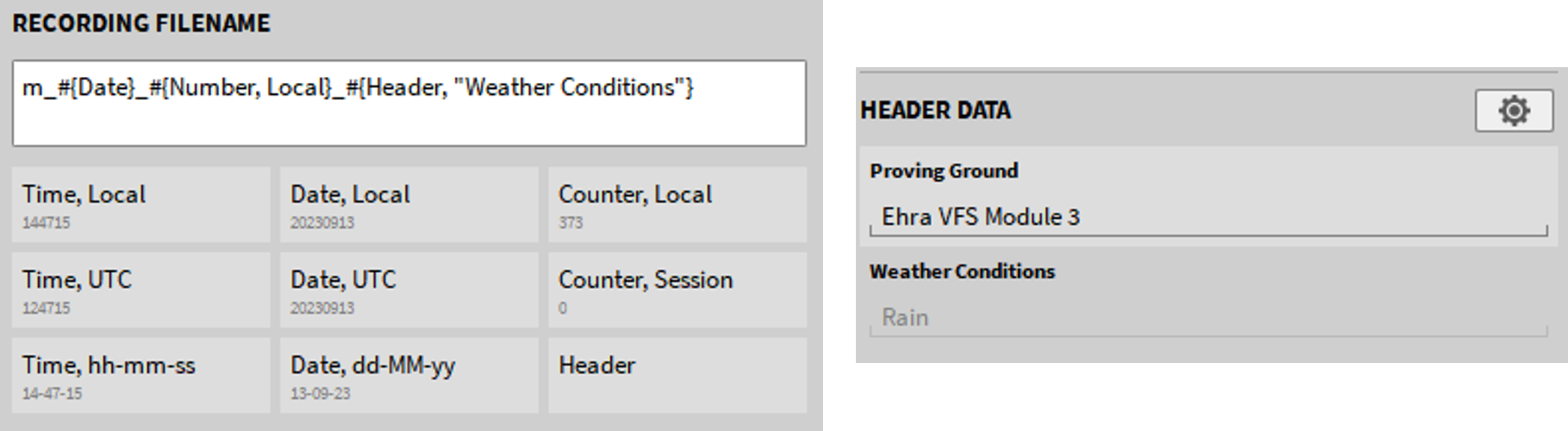
Fig. 143 Filename with header in formula
Time
Time, Local: the local time is used.
Time, UTC: the UTC time is used.
Time, hh-mm-ss: the time can be used in different formats.
Hours [h], minutes [m], seconds [s] and milliseconds [z] can be arranged individually. As separator [- . _] can be used, e.g. ss-mm-hh”, “mm_hh”, “ssmmhh”.
Note
The text File Start can be added, in order to guarantee the individual recording start for multi-file recordings. Example: #{Time, File Start, “hh-mm-ss”}.
Date
Date, Local: the local date is used.
Date, UTC: the UTC date is used.
Date, dd-MM-yy: the date can be used in different formats. Day, month and year can be arranged individually. As separator “-“ or none must be used, e.g. “yy-MM-dd”, “dd-MM”, “ddMMyy”.
Note
The placeholder letter for month (M) is written in capitals, to distinguish it from the placeholder for minutes (m).
Note
The text File Start can be added, in order to guarantee the individual date of recording start for multi-file recordings. Example: #{Date, File Start, “dd-MM-yy”}.
To specify a file name before recording start enable the button Ask for file name before recording start.

Fig. 144 Ask for file name before recording start button
If this button is enabled, a pop-up window (see Fig. 145) will appear where the file name can be entered.
Note
The recording only starts by clicking on the Record button (marked red in Fig. 145) in the pop-up window after entering the file name.
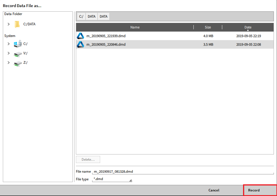
Fig. 145 Pop-up window to enter the file name before recording start
To open a file right after recording stop in the OXYGEN Viewer, activate the button Open recorded file in OXYGEN Viewer. Therefore, the last recorded measurement file will automatically be opened right after recording stop in the OXYGEN Viewer. OXYGEN can then be used for the next measurement, while the last recording can be analyzed.

Fig. 146 Button, to open the recorded file right after recording stop
Number
Counter, Local: this counter is persistent, meaning it will continue to increase also after OXYGEN or the whole system will be restarted. This counter can be reset by entering a desired number (e.g. 0) in the field for the Local Session Counter, see Fig. 142.
Counter, Session: this counter is dependent on the OXYGEN session and will increase every time a new measurement is started. It will be reset if OXYGEN is closed and started again.
Counter, Custom: this counter is a custom counter and must be adjusted manually to increase.
It is also possible to enter individual text in the text field. With these options it is possible to configure an individual name for standard or advanced use.
The filename preview shows the result of the configured file name.
Startup settings
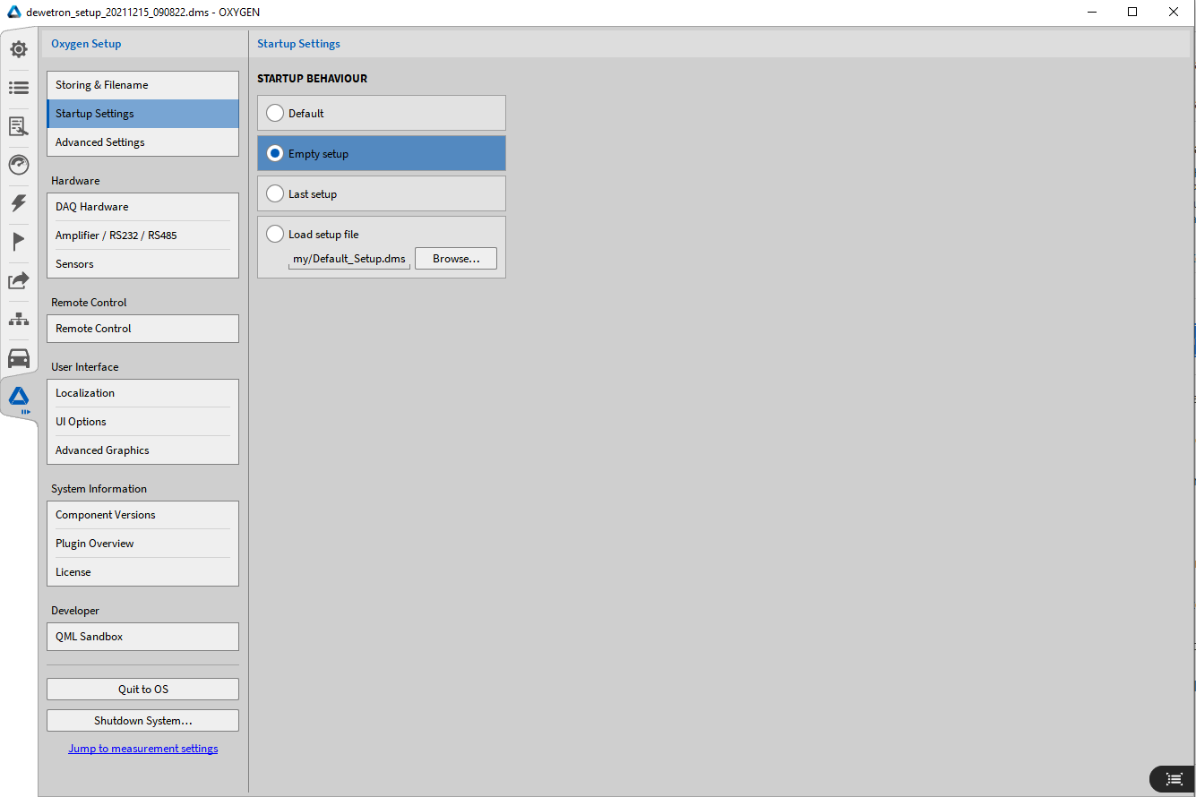
Fig. 147 Startup Behaviour settings
The user can select if the default setup file, an empty setup file, the last setup file or a user defined setup file shall be opened when OXYGEN is started (see Fig. 147).
Advanced settings
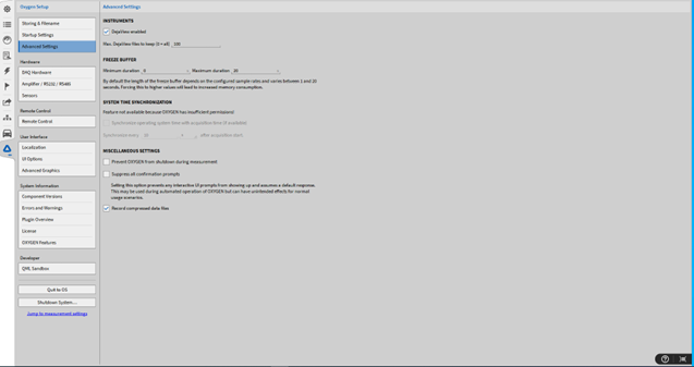
Fig. 148 Advanced settings
Instruments: In the Instruments section, DejaViewTM can be enabled/disabled. By default, DejaViewTM is always enabled. For a detailed description of DejaViewTM refer to DejaView™.
Freeze Buffer: The minimum and maximum duration of the freeze buffer can be changed manually here by entering a duration of 0-100 s. By default, the length of the buffer depends on the set sample rate and varies between 1-20 s. WARNING: A manual increase of the freeze buffer leads to a higher load of the main memory. Change with caution! If decreasing the memory consumption is necessary, lower the maximum duration of the freeze buffer.
System Time Synchronization: If an IRIG or GPS signal is received via a TRION-BASE (IRIG only), TRION-TIMING or TRION-VGPS module and if this signal is used for synchronization, the system time of the PC OXYGEN is running on can be set to this timing signal. For synchronization with an external timing source, refer to External Timing Source. The synchronization interval can be selected below and the minimum time interval is 10 seconds.
Miscellaneous settings: Closing OXYGEN by shutting down the system can be prevented by one setting here. The second setting allows to suppress confirmation messages like saving or discarding changes. This has advantages in automated operation, but can lead to undesired behavior in manual operation. The third setting is activated by default and allows to save recorded measurement files in a compressed data format. The data type for both compressed and uncompressed measurement files is .dmd in both cases. With this setting the size of the measurement file can be reduced up to 30%. However, the use of the compressed measurement files leads to a higher system load, if the system load is too high, the function should be deactivated.
Note
OXYGEN must be started with Administrator rights to use the system time synchronization function as this functionality changes the system settings of the PC. If OXYGEN is started without Administrator rights but this functionality is activated, the error message System time synchronization not allowed (see Fig. 149) will be displayed in the lower right corner of the software. note that this setting is not stored to a dms-setup file but only to the registry.

Fig. 149 Error message System time synchronization not allowed
Hardware
DAQ Hardware
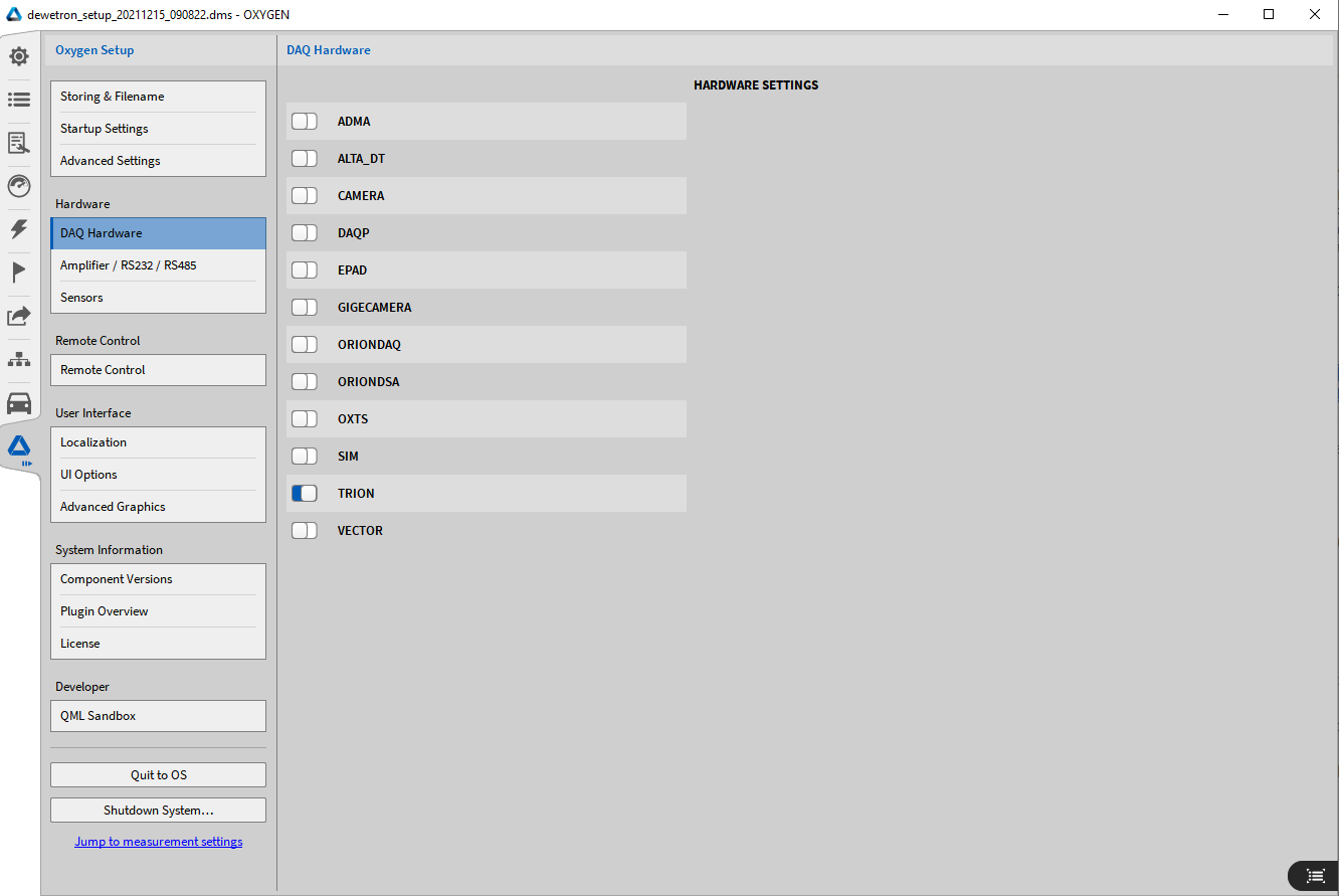
Fig. 150 DAQ Hardware settings
In the DAQ Hardware setup, the user can enable and disable the usability of different hardware series. For the detailed installing procedure of measurement hardware, refer to Hardware setup.
Amplifier / RS232 / RS485
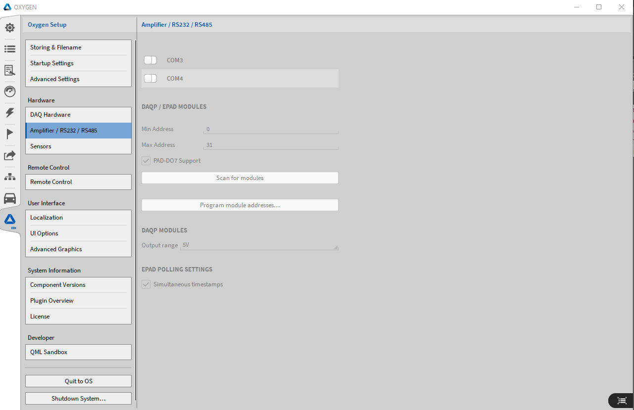
Fig. 151 Amplifier / RS232 / RS485
For more information, refer to Using EPAD2 with OXYGEN for EPADs and Using DAQP/HSI Modules with OXYGEN for DAQP/HSI modules.
Sensors
OXYGEN offers the possibility of a sensor database to hold all relevant information about the user’s sensors.
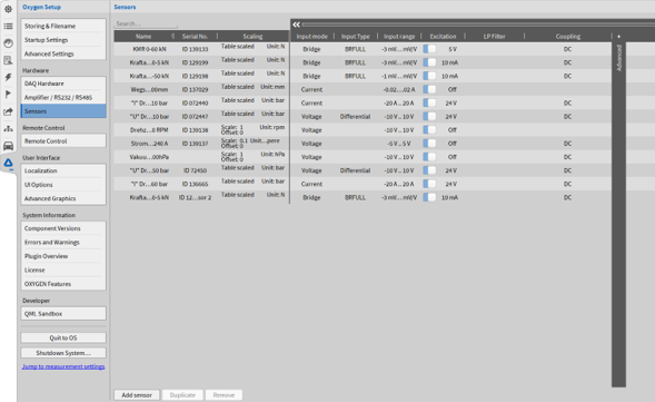
Fig. 152 Sensor Database
The sensor database can be found in the System Settings and provides a comfortable user interface with familiar sub-menus.
To add a new sensor, click on the Add sensor button in the lower left corner (marked red in Fig. 152). The properties of the sensor are the same which are also available in the channel settings (for detailed explanation see Changing the channel settings). By clicking on the properties, a small pop-up window will appear as seen in Fig. 153 where the following parameters can be edited:
Name: name of the sensor
Serial No.: add the serial number of the sensor
Scaling: add channel scaling or sensitivity; also 2-point, table or polynomial scaling is available
Measurement Input Properties (required by the sensor)
Input mode: define the input mode which is required by the sensor; choose between Voltage, Current, Bridge, Resistance, Potentiometer, Temperature and IEPE
Input Type: define the input type (depending on the input mode the input type varies)
Input range: define the input range (depending on the input mode the input range varies)
Excitation: choose excitation (off, Voltage, Current) and corresponding value
LP Filter: add optional lowpass filter, define the frequency, order (2, 4, 6, 8) and type (Bessel or Butterworth)
Coupling: choose coupling mode
And Bridge-Input Specific Settings
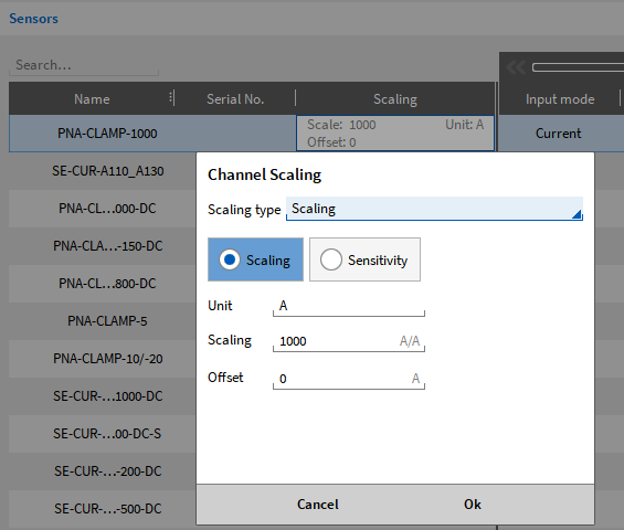
Fig. 153 Sensor database – pop-up window to change channel scaling
To duplicate or remove a sensor simply click on the respective sensor and on the Duplicate or Remove button as marked red in Fig. 152.
By clicking on + Advanced (see Fig. 154) in the parameter bar the advanced menu will open, and more properties can be added:
Bridge resistance
Bridge Sensor Offset
Bridge Shunt Target
Shunt Resistance
RTD Sensor Type
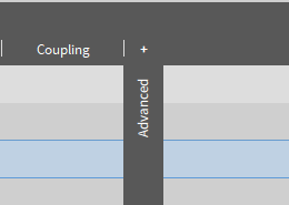
Fig. 154 Sensor database – open advanced menu
Bridge shunt target
The purpose of the bridge shunt target is to check Quarter Bridge, Half Bridge or Full Bridge wiring and determining the sensi¬tivity loss due to cable resistance. By applying a known resistor to the internal completion resistor, a known bridge unbalance can be simulated. In case of ideal wiring the measured unbalance will correlate exactly with the simulated unbalance. But in reality, cable resistance will decrease the measured value. By using the ratio between expected and measured unbalance this effect could be compensated.
The TRION(3)-18xx-MULTI measurement board supports a programmable shunt. The user can directly enter the “mV/V” or engineering unit within certain limits. The module calculates the appropriate resistor and applies it on demand. Sensor failures during test could easily be checked with this function. Simply compare the Shunt Cal result before and after the test run.
To apply a sensor to a channel, proceed with the following steps:
Enter the channel settings by clicking on the little gear of the individual channel in the channel list (pushbutton ⑪ in Fig. 175 or Table 10, for details see Changing the channel settings in the channel setup).
Click on the Choose sensor button in the upper right corner, seen in Fig. 155.
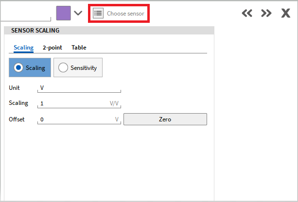
Fig. 155 Applying a sensor to a channel in the channel settings
A pop-up window will appear with a list of all defined sensors seen in Fig. 156.
Choose the desired sensor and click OK. The search field might ease the search for a specific sensor in the list.
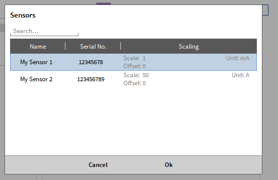
Fig. 156 Pop-up window to apply a sensor for a channel in the channel settings
The parameters of the sensor will be applied on the channel. This can be recognized by the name of the sensor, which will be displayed in the channel settings and in the channel, list seen in Fig. 157.
To remove an applied sensor from a channel simply click on the X button next to the sensor name in the channel settings (see Fig. 157).
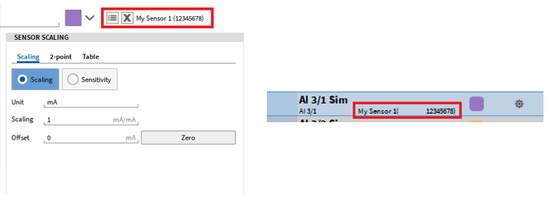
Fig. 157 Name of chosen sensor for the channel seen in the channel list and channel settings
Note
Only analog sensors, including XR modules, are supported in the database (no encoder).
Whenever the database is changed, the sensors on the assigned channels do not update automatically and must be assigned again.
An .xml file will be created with the sensor information, which can also be edited externally in a third-party software.
The name of the xml-file is sensor_db.xml and can be found in the following directory: %PUBLIC%\Documents\Dewetron\OXYGEN.
It is also possible to transfer set sensors directly from the channel list to the sensor database or to overwrite existing sensors from the database (see Fig. 158).
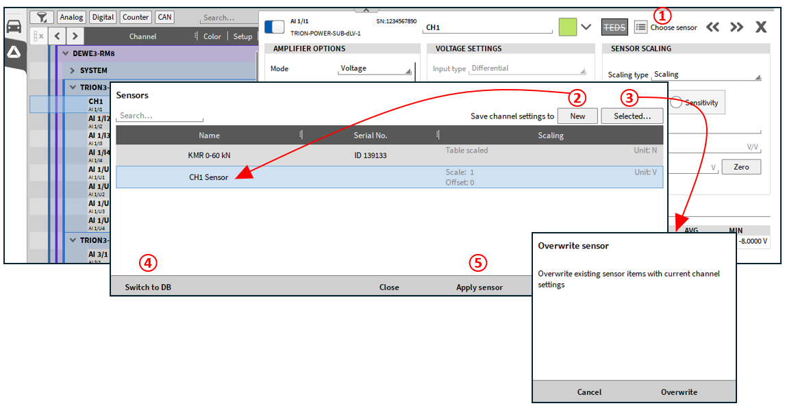
Fig. 158 Sensor database via channel list
No. |
Function |
Description |
|---|---|---|
1 |
Choose sensor |
Clicking on the button opens the sensor database. It is possible to select a sensor from the database in order to transfer the settings to the selected channel, or to create a new sensor in the database with the current settings of the selected channel or to overwrite an existing one. |
2 |
New |
When you click on the “New” button, a new sensor is created in the sensor database according to the settings of the selected channel. An automatic name is assigned that corresponds to the channel name, this name can be changed later in the sensor database. |
3 |
Selected |
Overwrites the selected sensor in the list of the sensor database with the settings of the currently selected channel in the channel list. After clicking on the corresponding button, a window appears indicating that  the existing data for the selected sensor will be overwritten after clicking on “Overwrite”. |
4 |
Switch to DB |
Switch to the sensor database (see Fig. 158). |
5 |
Apply sensor |
After clicking on the “Apply Sensor” button, the settings of the selected sensor are applied from the sensor database to the selected channel in the channel list. |
Remote control
If remote control is enabled, the Lock Screen button will change to a Remote Control indicator and marks if OXYGEN is controlled by remote (see Fig. 159).

Fig. 159 Remote Control indicator
SCPI over Ethernet
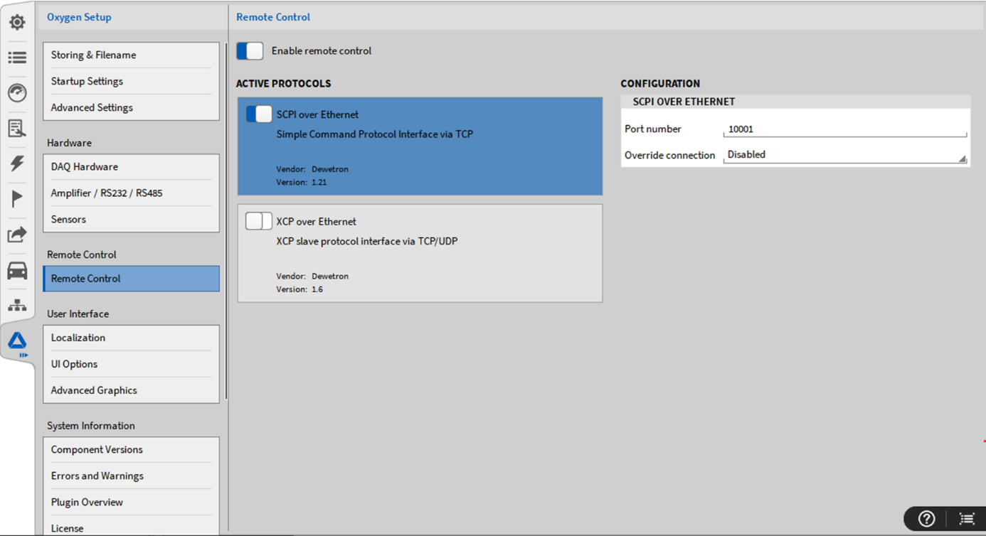
Fig. 160 Remote Control – SCPI over Ethernet menu
OXYGEN can be controlled by remote via SCPI. To do so, the Enable remote control button (see Fig. 160) must be switched on and SCPI over Ethernet must be enabled. The Connection mode setting Single client ensures that no other device can connect once a SCPI connection has been established. The Multiple Client Connection mode enables multiple SCPI client to connect.
For detailed instructions and programming examples, refer to the manual OXYGEN Remote Control-SCPI Version Vx.x which is available on the DEWETRON CCC portal (https://ccc.dewetron.com/).
For additional information about typical performance and other basic points, refer to Table 9.
OXYGEN-GO app
OXYGEN-GO will be an app for your mobile device that can connect to OXYGEN running on your DAQ system.
The app connects to OXYGEN using the SCPI connection. For a connection the mobile device must be in the same network as the DAQ system. To connect you can scan the QR-code in the Remote Control in OXYGEN with the app, or connect via IP-address and port.
With the OXYGEN-GO app some basic channel settings can be changed, a input preview is available and a recording can be started/stopped.
XCP over Ethernet
Note
This is an optional feature and requires a license.
OXYGEN can be controlled via XCP over Ethernet. To do so, the Enable remote control button must be switched on and XCP over Ethernet must be enabled (see Fig. 161).
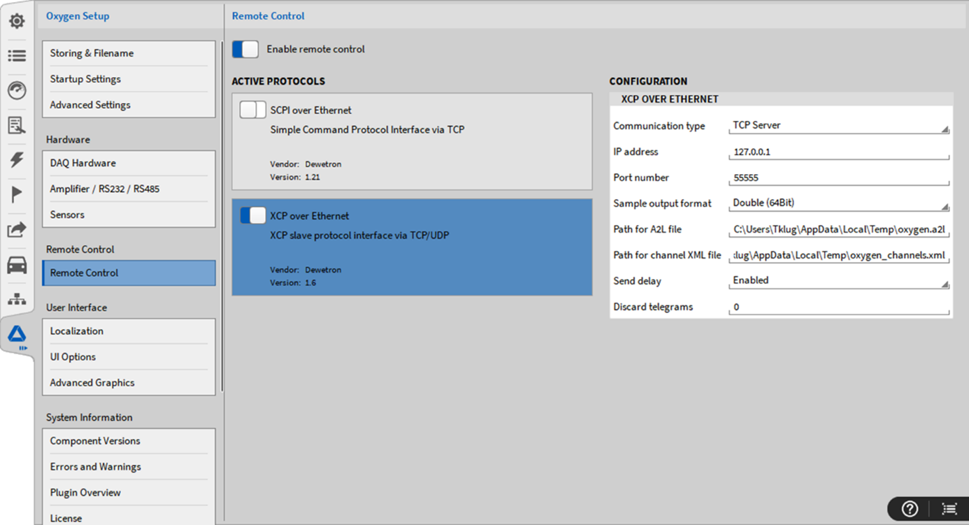
Fig. 161 Remote Control – XCP over Ethernet menu
Within OXYGEN, the following XCP settings can be edited:
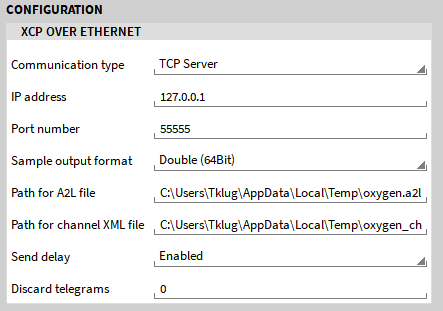
Fig. 162 Configuration for XCP over Ethernet
Communication Type: TCP server or UDP server
IP address of the OXYGEN device
Port Number
Output format: Double (64bit) or Float (32bit)
A2L File Path: The path the a2l-file is stored to. An a2l-file is automatically generated when XCP remote control is enabled and when OXYGEN is started
XML File Path: The path the xml-file is stored to. A xml-file is automatically generated when XCP remote control is enabled and when OXYGEN is started
Send delay: Can be set to enabled/disabled and refers to the number of telegrams discarded at the start.
Discard telegrams: Can be set between 0 and 20 and defines the number of telegrams discarded at the start.
Max. packet size: Maxium size of UDP/TCP packets in bytes. Leave at 0 for default settings. This value needs to be set if the XCP master cannot handle packets of aritrary size.
Note
Be aware that the directory C:/Temp the a2l-file and the xml-file is stored to is not created automatically. Create the directory C:/Temp manually or change the path to an existing directory.
A user instruction to setup a remote control via CANape can be found in the document DEWETRON_OXYGEN_XCP_User_Instructions_Vx.x which is available on the DEWETRON CCC portal (https://ccc.dewetron.com/).
For additional information about typical performance and other basic points, refer to Table 9.
Usage SCPI and XCP simultaneously
It is possible to use the SCPI and the XCP plugin both simultaneously. Just enable both plugins and follow the instructions for SCPI from SCPI over Ethernet and the instructions for XCP in XCP over Ethernet.
As stated above, detailed and latest user manuals for both plugins are available on the DEWETRON CCC portal:
For detailed SPCI instructions and programming examples, refer to the manual OXYGEN Remote Control-SCPI Version Vx.x which is available on the DEWETRON CCC portal (https://ccc.dewetron.com/).
A user instruction to setup a remote control via CANape can be found in the document DEWETRON_OXYGEN_XCP_User_Instructions_Vx.x which is available on the DEWETRON CCC portal (https://ccc.dewetron.com/).
Streaming interfaces
EtherCAT slave
Note
This is an optional feature and requires a license.
Using the EtherCAT slave subsystem, an OXYGEN system is able to provide timestamped periodic measurement values to an EtherCAT master. The most important control features as well as some status information are provided as well.
OXYGEN EtherCAT functionality currently only supports TRION-ETHERCAT boards.
For detailed instructions, refer to the manual OXYGEN EtherCAT Slave Vx.x. which is available on the DEWETRON CCC portal (https://ccc.dewetron.com/).
For additional information about typical performance and other basic points, refer to Table 9.
Data stream plugin
Note
This is an optional feature and requires a license.
The OXYGEN Data Stream plugin provides the following features:
High Speed data access
Efficient raw data transfer
Multi data stream support
Multi network port support
Configurable via SCPI
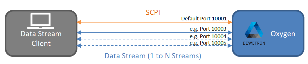
Fig. 163 Data stream plugin – overview
For detailed instructions and programming examples, refer to the manual OXYGEN CSV Plugin Vx.x which is available on the DEWETRON CCC portal (https://ccc.dewetron.com/).
For additional information about typical performance and other basic points, refer to Table 9.
Ethernet sender plugin
Note
This feature is included in the installer by default.
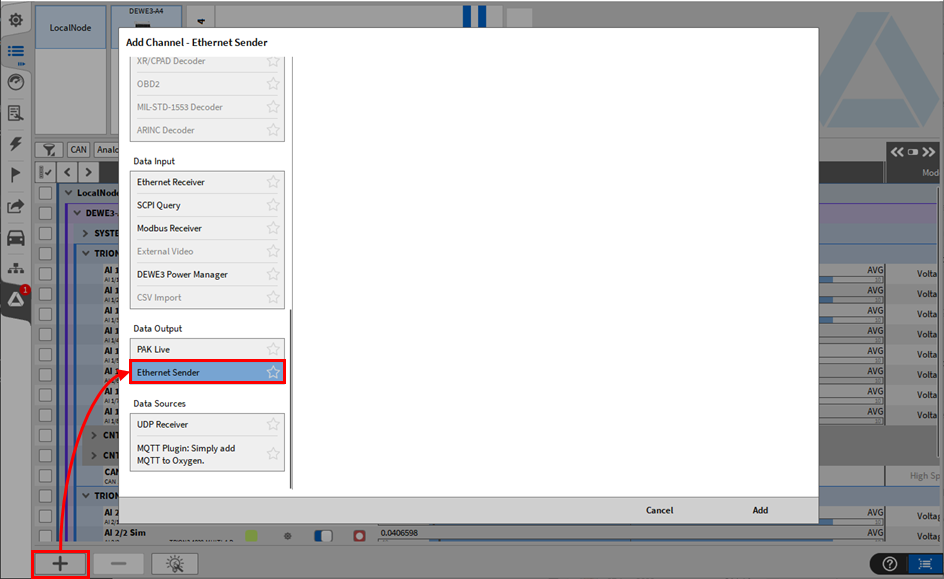
Fig. 164 Pop-up window to create an Ethernet sender
An Ethernet sender can be created and configured by pressing the Add button in the lower left corner of the Data Channels menu (marked red in Fig. 164).
For details about the Ethernet Sender plugin refer to the DEWETRON_OXYGEN_Ethernet_Sender_Vx.x Manual which is available on the DEWETRON CCC portal (https://ccc.dewetron.com/).
Remote control and streaming interfaces
The following Table 9 provides an overview and comparison about the licensing, typical performance and other additional information of the different remote control and streaming interfaces.
Interface option |
Included in OXYGEN |
Interface |
Typ. application |
Typ. performance |
|---|---|---|---|---|
SCPI |
Yes |
Standard Ethernet |
Fetching of actual values loading setup, application control, application |
~50 S/s with 50 channels; up to 10 kS/s with 10 channels (buffered reading “ELOG”) |
XCP Slave |
License required |
Standard Ethernet |
Stream of measurement values, basic recording control; only compatible with CANape yet; INCA compatibility is in progress |
~2 MS/s with 8 channels |
EtherCAT |
License required |
TRION EtherCAT |
EtherCAT testbed environment; Provide measurement values on the EtherCAT bus with PDO mechanism |
~1 kS/s with 100 channels |
Data Stream |
License required |
Standard Ethernet |
Live processing of raw and full speed data in 3rd party application; uses native TCP/IP sockets for data transfer; multiple streams can be created |
~100 kS/s with 350 channels or ~2 MS/s with 12 channels |
Ethernet Sender |
Yes |
Standard Ethernet |
Send data with timestamps |
1-100 Hz |
OPC UA |
License required |
Standard Ethernet |
Open Platform Unified Architecture |
Send 20 Hz; Receive 1 kHz |
Modbus |
License required |
Standard Ethernet |
Industrial automation protocol |
Send 100 Hz; Receive 100 Hz |
Typical I/O delay is 100-200 ms within all interface options |
||||
User interface
Localization
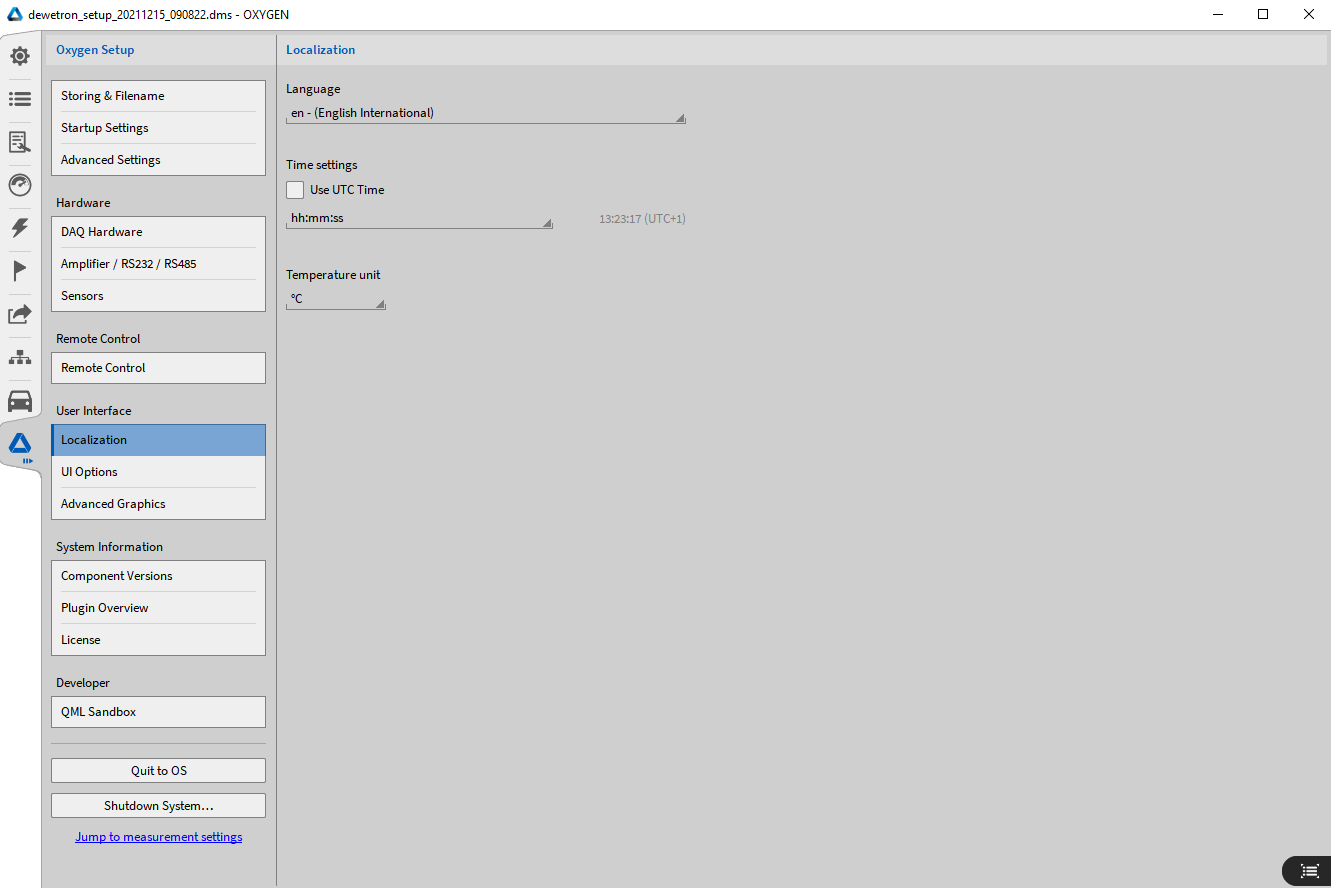
Fig. 165 Localization – settings
The Localization menu allows users to adjust the following settings:
Language: Change the software language.
Time settings: Set the time to UTC and choose the desired time format.
Temperature unit: Select between Celsius and Fahrenheit.
Thousands separator: Define a separator to improve the readability of large numbers. This setting applies to the Analog Meter, Digital Meter, and Table instruments.
UI options
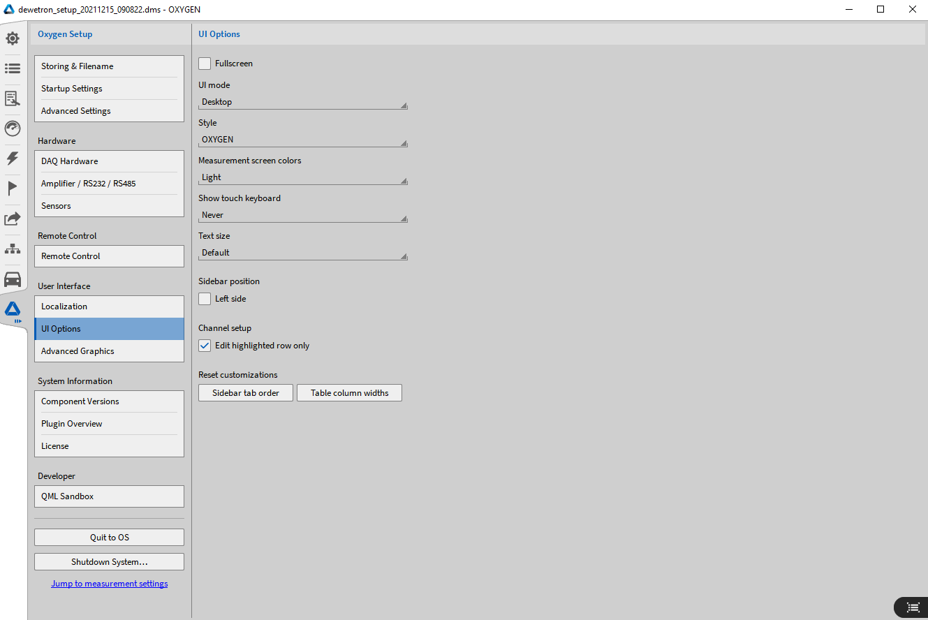
Fig. 166 UI Options – settings
In the UI Options, the user can change different settings of the UI appearance:
UI mode will change the size of the icons and adjust it for different PC types
Style will change the menu style
Color Scheme will change the color scheme of the software. A light and a dark mode are available.
Show touch keyboard regulates the appearance of a touch keyboard
Text size changes the text size in OXYGEN
Sidebar position: If Left side is selected, the sidebars will swap and the Reset button will set the menu order to the default order if changes have been made. For customizing the menu order, refer to Custom ordering of menu locations.
Channel setup: Edit highlighted row only: When this option is selected and the user selects a channel in the Channel Setup, the selected channel will only be highlighted when the user clicks on the channel name and a second click for changing the channel name is necessary. When this option is NOT selected, the user will be able to change the channel name by a single click on the channel name.
Advanced graphics
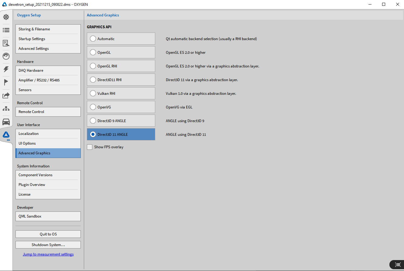
Fig. 167 Advanced graphics – settings
In this section the user can change the graphic framework, if there any problems with the graphic occurred. Contact us for more information or any help.
System information
Component version
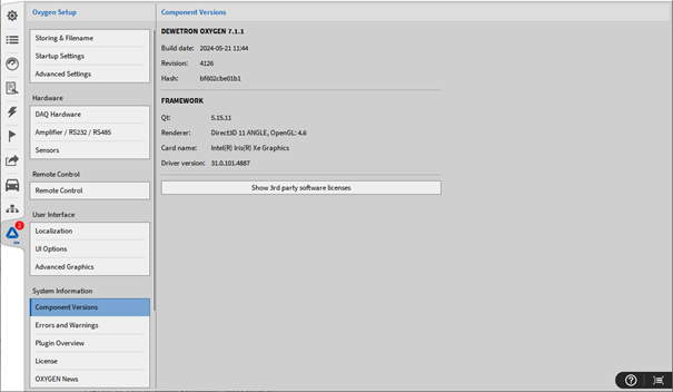
Fig. 168 Component Versions – overview
In this section the versions of all components and 3rd party licenses are displayed.
Errors and warnings
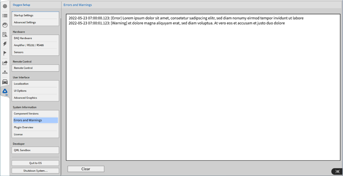
Fig. 169 Errors and warnings
This menu displays all raised errors and warnings as a list with time stamps.
Plugin overview
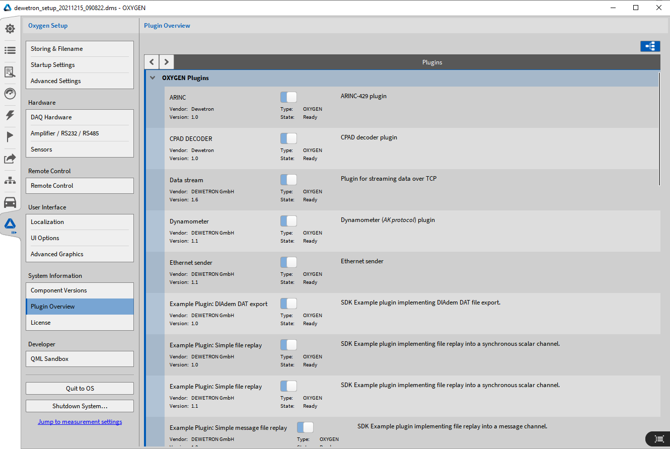
Fig. 170 Plugin overview
This menu displays an overview of all active plugins. These cannot be deactived.
License
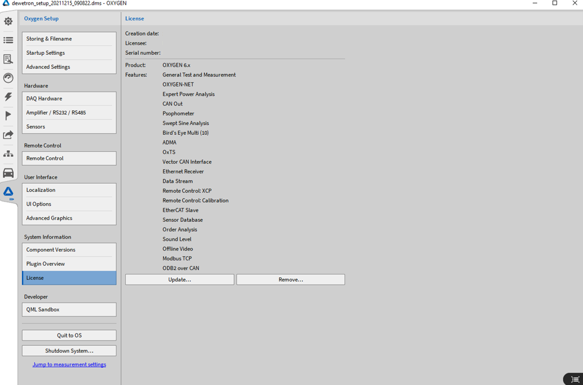
Fig. 171 License overview
Here you can find some information about the license and the active features. Additionally, the license can be updated by clicking on the Update… button and selecting the new license file. OXYGEN must be restarted. To remove the current license, click on Remove…, OXYGEN will switch into the Evaluation mode.
Note
A license file for OXYGEN 5.x is not valid for OXYGEN 6.x
OXYGEN News
In the OXYGEN News tab you can view information on known problems and activate automatic updates for these as well as a list of available features.
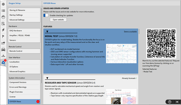
Fig. 172 License overview
Shutdown
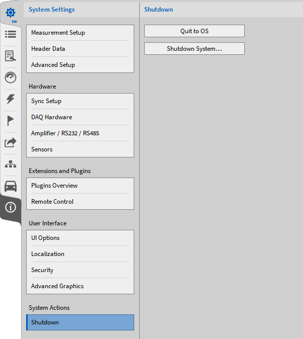
Fig. 173 System settings Shutdown – overview
In the Shutdown menu, the user can terminate OXYGEN and return to the operating system or shut down the whole system.