Hardware setup
The usage of different hardware types can be enabled and disabled in the DAQ Hardware setup which can be found in the System Settings. To access, the System Settings must be expanded to the full screen.
Using TRION hardware with OXYGEN
Make sure that the driver for the TRION-hardware is installed. The installer is named DEWETRON‑TRION-Applications-x64.exe and can be found in the folder \files\drivers\2_daqboards\dewetron\trion_driver\DEWETRON TRION Rx.x of the Install Media USB stick which is delivered with the measurement system.
If the driver was installed correctly, the DEWE2 Explorer will be available in Windows start menu.
Go to the DAQ Hardware setup in the System Settings and make sure that the TRION Series is enabled (see Fig. 32). Changes take effect on application restart.
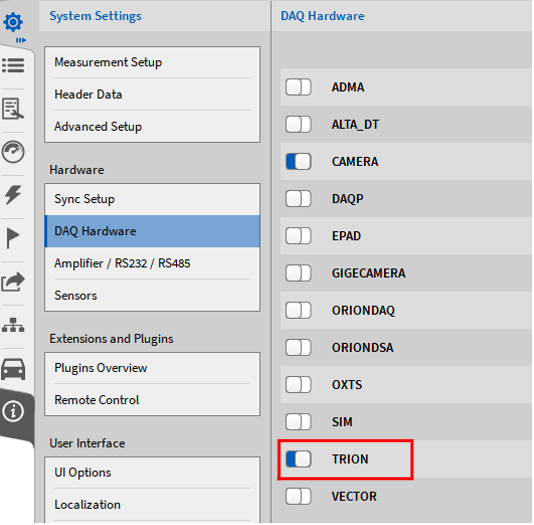
Fig. 32 Enabling the TRION Series in the DAQ Hardware setup
The channels of the connected TRION hardware will now be visible and editable in the Channel List (see Fig. 33):
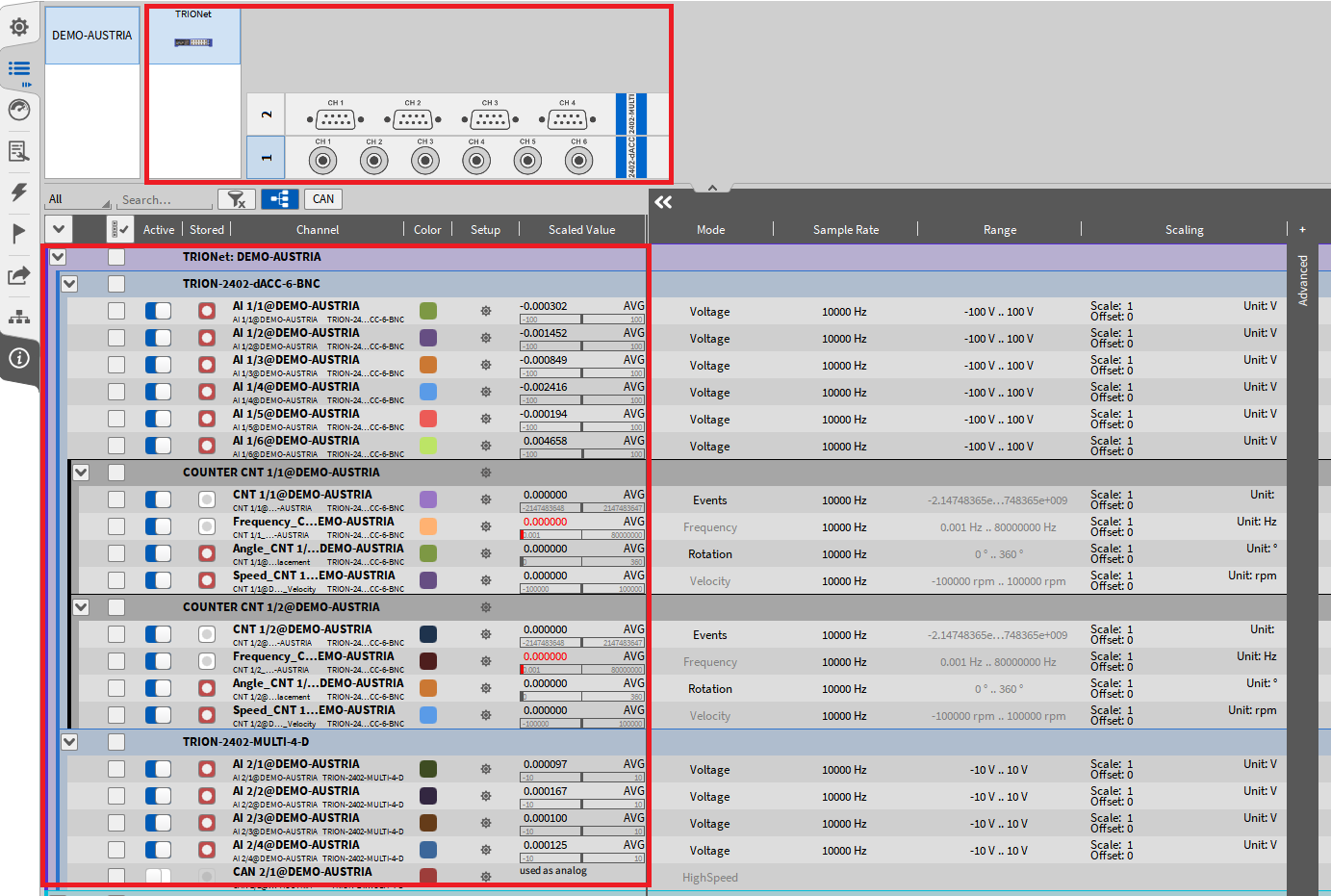
Fig. 33 Overview of connected TRION hardware in the Channel List
Using TRION3-AOUT-8 in OXYGEN
This section will explain the software functions for the TRION3-AOUT module in OXYGEN. In order to use these functionalities, the TRION3-AOUT in combination with a TRION3-18xx-MULTI module and OXYGEN 5.4 version or above are required. The configuration of the two modules can only be done at factory and cannot be changed by the user.
For a detailed explanation of the hardware functionalities refer to the TRION3-AOUT datasheet, which can be found on our website www.DEWETRON.com.
The TRION3-AOUT-8 module has two functions:
Conditioned signal output
Calculated channel output
Conditioned signal output
A direct or processed output of each conditioned analog input of the TRION3-18xx-MULTI is available here. This can be a ±5 V, ±10 V or 0-10 V analog signal as direct output or RMS or average value for the same ranges as processed output.
Calculated channel output
Any channel or the TRION3-18xx-MULTI can be used for basic calculations on the FPGA and output the result as a ±5 V, ±10 V or 0-10 V analog signal.
These two functions are available through 4 different modes, which are available in OXYGEN:
Monitor Output
Math Output
Constant Output
Function Generator
The small gear button, seen in Fig. 34 opens the channel setting of each channel.
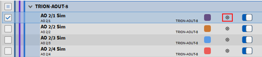
Fig. 34 Opening the channel settings of the TRION3-AOUT module
The settings are divided in 3 sections seen in Fig. 35 output amplifier options, mode settings and scaling information.
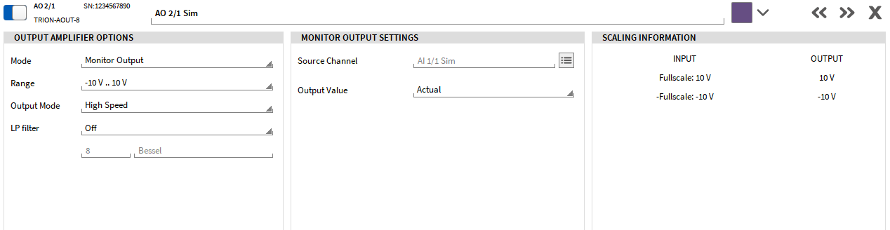
Fig. 35 Channel settings of the TRION3-AOUT module
In the output amplifier options the according Mode can be selected. Following, each Mode and the according settings will be explained.
Also, the Range of the output can be selected here, whereby ±5 V, ±10 V, 0-5 V, 0-10 V, ±30 mA or 0-30 mA are available.
For the Output Mode two different options can be selected: High-Speed or High-Resolution. The following table will explain the differences between these two modes.
High-speed mode |
High-resolution mode |
|
|---|---|---|
Update rate |
2.5 MS/s |
500 kS/s |
Resolution |
16-bit |
32-bit |
Latency |
<5 µs |
<100 µs |
A lowpass filter can also be selected in this section with the cut-off frequency and the filter characteristic.
If the range of the TRION3-18xx-MULTI module exceeds the possible output range of the TRION3-AOUT module, the signal will be scaled accordingly. This scaling information can be seen in the Scaling Information section. An example of an exceeded range can be seen in the following Fig. 36.
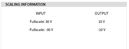
Fig. 36 Scaling information for an exceeded range
Monitor Output
Fig. 37 shows the available settings for the Monitor Output mode. This mode enables to monitor an input channel of the TRION3-18xx-MULTI module as different output values. The source channel can be selected by clicking on the button marked red in Fig. 37. Fig. 38 shows the dialog which opens to select the corresponding source channel. Only one channel can be selected.
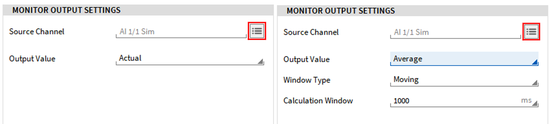
Fig. 37 Monitor Output settings
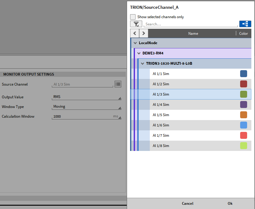
Fig. 38 Source channel selection for the Monitor Output Mode
It is possible to output the actual value or the average or RMS value of an input channel of the TRION3-18xx-MULTI module. If the average or RMS is selected, two additional settings are available as seen in Fig. 37 on the right side. The Window Type can be Fixed or Moving and for the Calculation Window a value can be chosen from the dropdown list or a value can be entered manually.
Math Output
Fig. 39 shows the settings for the Math Output mode. Again, two source channels can be selected by clicking on the button marked red in Fig. 39. The following three Math Operations are available for the two source channels:
A + B
A – B
A * B
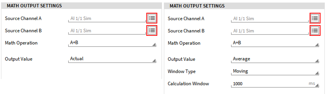
Fig. 39 Math Output settings
It is possible to output the actual value of the operation result or the average or RMS value. If the average or RMS is selected, two additional settings are available as seen in Fig. 39 on the right side. The Window Type can be Fixed or Moving and for the Calculation Window a value can be chosen from the dropdown list or a value can be entered manually.
Constant Output
Fig. 40 shows the setting for the Constant Output mode. The Source Channel cannot be selected, since for the constant output this is not necessary. Depending on the Range, which is selected in the Output Amplifier Options (see Fig. 35 a Constant Value can be entered, which lies within the range. The slider can be used to set a value, or it can be entered manually in the provided field.
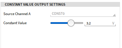
Fig. 40 Constant Output settings
Function Generator
As a last mode the Function Generator is available. The different settings can be seen in Fig. 41
Waveform: sine, square or triangle waveform can be selected or an individual pattern, which can be defined in the Custom Waveform Store section (see Fig. 41). For a more detailed explanation see Custom Waveform Store.
Frequency: the frequency can be selected from the dropdown list or an individual value can be entered between 0.001 Hz and 1 MHz.
Amplitude: the amplitude can be between 0–10 V or 0–30 mA as peak or RMS value.
Offset: an offset between ±10 V or ±30 mA can be defined.
Phase: a phase between ±180° can be defined.
Symmetry/Dutycycle: this option is only available for a triangle or square waveform and can be defined between 0.001–100 %.
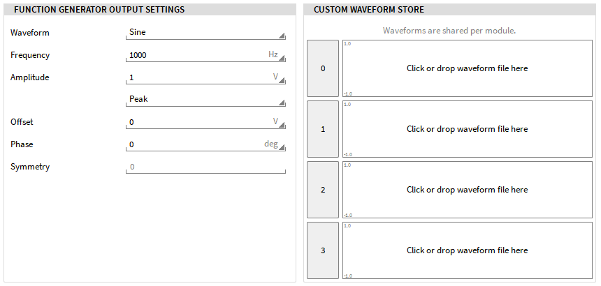
Fig. 41 Function Generator settings
Custom Waveform Store
If a custom waveform wants to be used, Pattern 0-3 must be selected as Waveform in the Function Generator Output settings. In the section Custom Waveform Store 4 different waveforms can be defined accordingly. Only one waveform can be selected per channel. A custom waveform file can either be dragged and dropped to one of the provided fields or selected by clicking on the filed directly and a file dialog will open. The waveforms are also shared per module; therefore 4 different waveforms can be dropped and are available on each channel of that module. These waveforms are also saved in the setup file.
There are some rules for the waveform file:
The file must be a .csv format
Each row is one value or sample
Only values between -1 and 1 are allowed
The separator must be a . (dot)
A maximum of 16384 rows are allowed
The defined waveform corresponds to one period and will be repeated periodically.
Fig. 42 shows 3 different custom waveforms and Pattern2 is currently selected as Waveform in the settings.
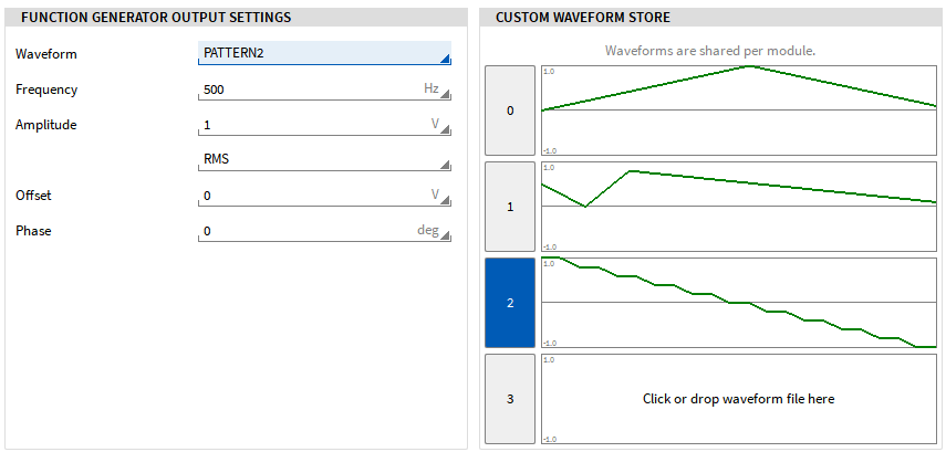
Fig. 42 Custom Waveform for the Function Generator mode
Stream Output / File Replay
The Stream Output functionality can be used to output scalar channels via the analog output channels of the TRION3-AOUT board, this is also possible with channels of a previously recorded OXYGEN file. This mode is also supported by the TRION3-AOUT as a standalone module.
To use this mode, the software must be in LIVE mode (data acquisition) or REC mode and is not supported in PLAY mode.
To use this mode, follow these steps:
Open the channel settings of each channel, that should be used for the stream output (see Fig. 43).
Change the mode to StreamOutput and select the desired range and output signal (voltage or current). For the output of channels of a previously recorded OXYGEN file, select the data source Replay in the Stream Output Settings, all further settings are done in the Stream Output instrument. For the output of any scalar OXYGEN channel, specify “Live” as data source, as well as the source channel in the Stream Output Settings and define the delay time (0.5 .. 10 s), as well as a necessary conversion factor or offset.
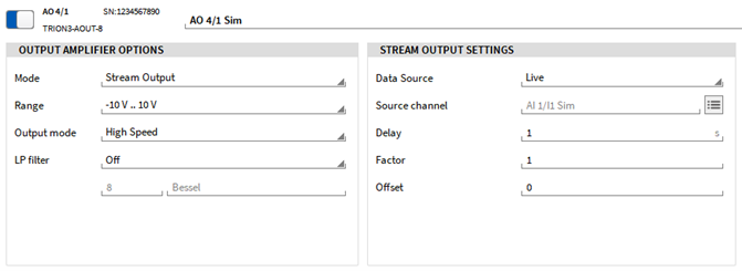
Fig. 43 Channel settings for the Stream Output functionality
To replay channels of a previously recorded OXYGEN file, go to your measurement screen and open the small Instrument menu. A separate instrument exists for loading the data file and choosing the channels to be output/restreamed. As seen in Fig. 44, drag and drop the instrument on your measurement screen, adjust the size and place it to a desired location.
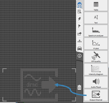
Fig. 44 Use Stream Output Instrument on the measurement screen
Open the small Data Channel list in order to choose the analog output channels, which should be used for the Stream Output functionality. Select the instrument and click on the respective channels or drag and drop the channels into the instrument. Up to 8 channels can be used in one instrument.
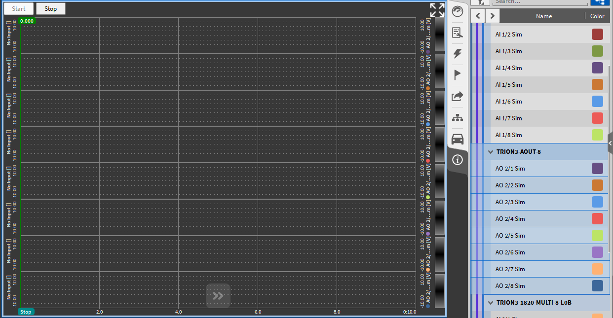
Fig. 45 Choosing the analog output channels
Note
Only channels with the mode StreamOutput can be used in the instrument (see above). If analog output channels are used, which have another mode selected in the channel settings, a warning appears in the instrument itself, see Fig. 46. In this case, open the channel settings of the used channel and check the selected mode.
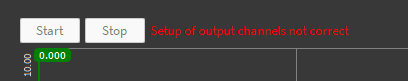
Fig. 46 Warning when using analog output channel with wrong mode in Stream Output Instrument
To load a data file and choose the channels to be output, open the instrument properties by either double-clicking on the instrument itself or selecting the instrument and open the Instrument Properties menu tab (see Fig. 47).
① Click on Browse to choose the .dmd file to be replayed.
② Assign the input channel to the output channel.
③ Adjust the output scaling factor.
④ Adjust the output offset, if desired.
⑤ Loop the playback, otherwise the signal will only be output once.
⑥ Use the cursors to replay only a certain part of the data file.
⑦ Start/stop/pause the playback.
⑧ Playback mode “Replay” is used to play back channels of a previously recorded OXYGEN file. (see Fig. 47) Playback mode “Live” is used to play back scalar channels of the current measurement (see Fig. 48), no data is displayed in the instrument. In “Live” mode, the instrument is only used to set the channels to be transmitted, which are directly output as AOUT channels with the set delay time.
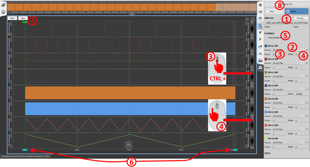
Fig. 47 Stream Output Instrument: Instrument properties (Replay)
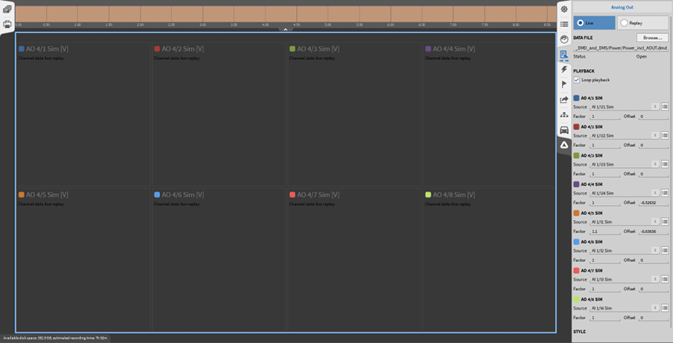
Fig. 48 Stream Output Instrument: Instrument properties (Live)
Channel SUM Mode
The channel mode “Channel Sum”, enables the creation of a linear equation of up to 8 AIs and can output this via an AO channel. To use this feature, a firmware update must be made. Useful for shaker control.

For the first 8 analog inputs a scaling between -10 and 10 can be chosen ① denoted in the equation before as X_i. To scale the resulting formula the output scale can be set between -100 and 100 ② denoted before as Y. Lastly, the output value type can be selected as actual, average or RMS ③. When choosing Average or RMS, the window type ④ can be defined as moving or fixed.
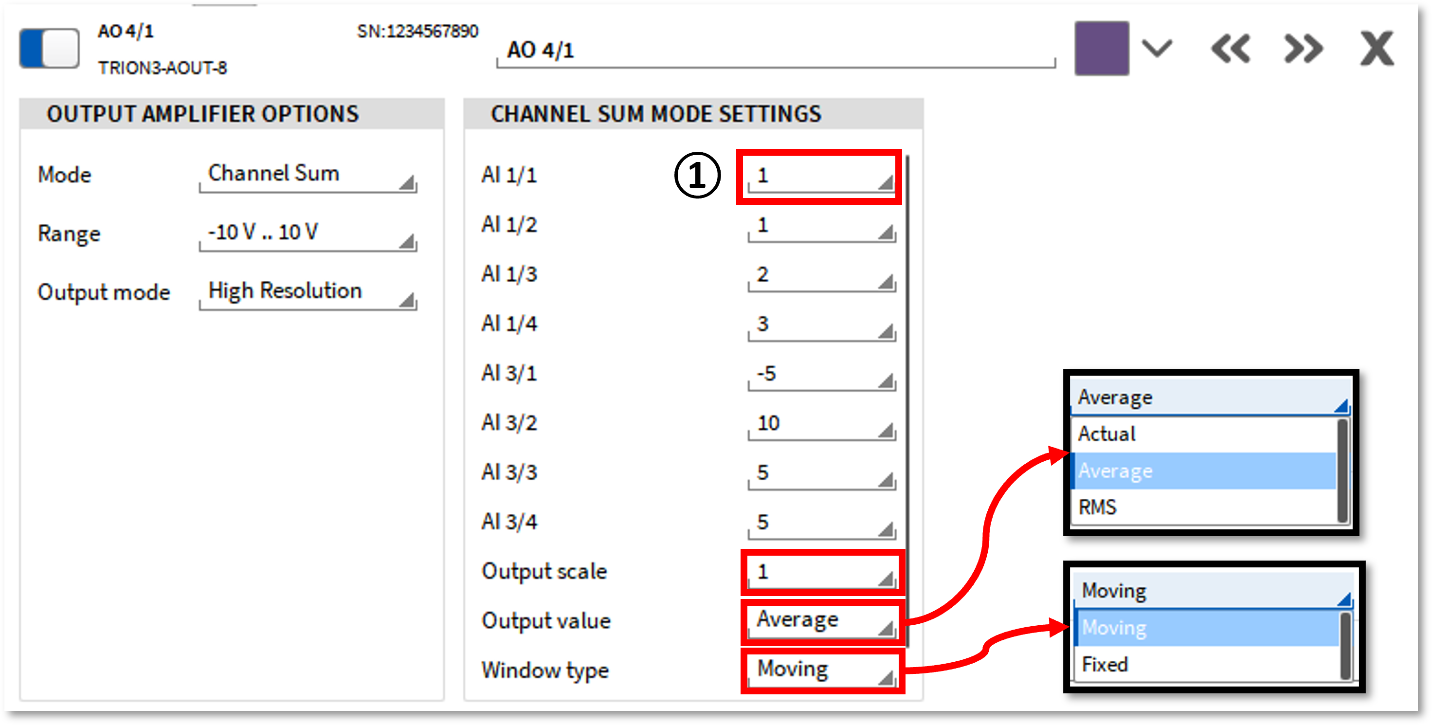
Fig. 49 Channel Sum mode settings
Using TRIONet in OXYGEN
In addition to the steps explained in Using TRION hardware with OXYGEN, the following steps must be carried out if TRION hardware is used in combination with a TRIONet.
Choose ‘Auto’ from the ‘Network Interfaces’ drop-down menu (see Using TRION hardware with OXYGEN). This will scan all ethernet ports and automatically detect the TRIONet device.
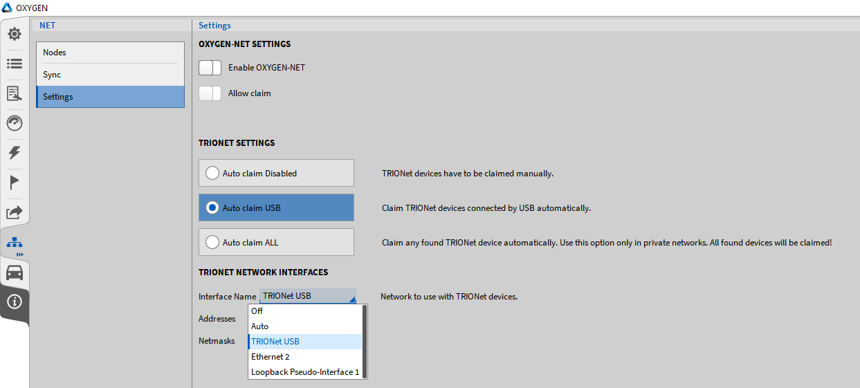
Fig. 50 Network Interface settings
The IP-address of the adapter is shown in the field below (see Fig. 51)
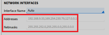
Fig. 51 IP addresses of connected TRIONets
Now switching to Channel List will display the TRIONet and installed modules
Note
Besides the TRION hardware driver, there is no additional driver required to use a TRIONet with your measurement system. For additional information about the TRIONet and troubleshooting, please refer to the TRIONet Technical Reference Manual.
Using EPAD2 with OXYGEN
Using EPAD2 with OXYGEN on a DEWE or DEWE2 system
For connecting an EPAD2 module with your hardware, the DEWE and DEWE2 series products (except TRIONet) have a connector on the housing marked with the word EPAD (see Fig. 52).
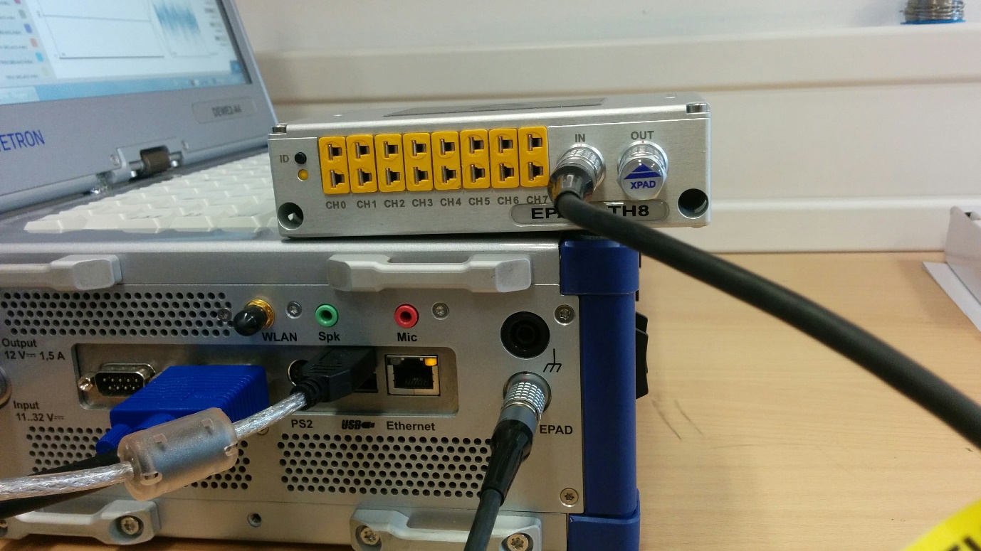
Fig. 52 Connection of EPAD modules
Expand the System Settings menu fully across the screen
Select the DAQ Hardware section and ensure the slider button next to the EPAD Series is activated (see Fig. 53). Changes take effect on application restart.
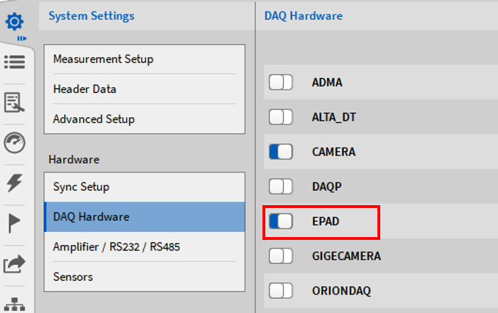
Fig. 53 Enabling the EPAD Series in the DAQ Hardware setup
Select the proper Serial Port for your EPAD2 module by clicking on the Select ports… button (see Fig. 54). Systems in Europe are typically assigned to COM2 and systems in the USA are typically assigned to COM3).
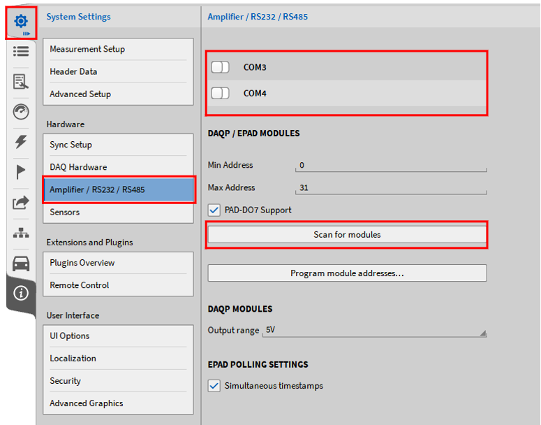
Fig. 54 Selection of the proper COM port
Press the Scan for modules button (see Fig. 55). The system will scan the selected Serial Port for any present EPAD2 modules. The status can be seen in the lower right corner of the software.
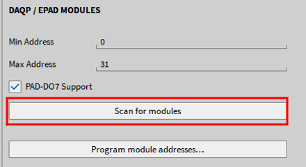
Fig. 55 Scan for modules button
If an EPAD2 module is found, the user will be presented with a message in the lower right corner of the software (see Fig. 56) stating that the software has found an EPAD2 module.

Fig. 56 EPAD found message
If you have multiple EPAD2 modules daisy chained together, the user can select the Program module addresses… button (see Fig. 57).
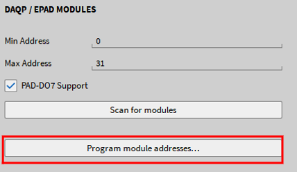
Fig. 57 Program module addresses button
Next, select the starting EPAD2 address (cannot be 0) and then select Start programming (see Fig. 58).
Once the programming has begun, the software will ask you to press the black ID button (see Fig. 59) on the first EPAD2 module. Then it will increment the address in the software by one. At this point you will press the second EPAD2s’ black ID button and so on.
When finished programming, select the Stop Programming button (see Fig. 58).
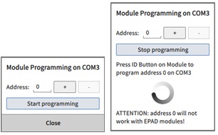
Fig. 58 EPAD-programming procedure
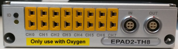
Fig. 59 Front of an EPAD2 module
Using EPADS with OXYGEN via EPAD2-USB module
EPAD2 modules can also be used as stand-alone measurement solution (CVT-Logger) without DEWE or DEWE2 hardware. Therefore, they can be connected via the EPAD2-USB module to the measurement PC. This is also a solution for using EPAD2 modules in combination with a TRIONet which has no EPAD connector.
Make sure that the driver for the EPAD2-USB module is installed on the measurement PC. The setup.exe file can be found in the folder \files\drivers3_communication\dewetron_usb of the Install Media USB stick which is delivered with the EPAD2-USB module. After finishing the driver installation, the EPAD2 module can be programmed in OXYGEN in the same manner which is explained in General settings. The correct COM port can be found in the Device Manager of your PC in this case. The COM port which is called TUSB3410 DEVICE is the correct one (see Fig. 60).
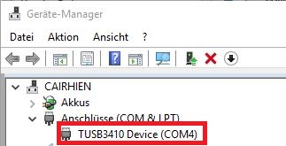
Fig. 60 COM port section in the Device Manager
Troubleshooting
If no EPAD module is found during the scan for modules although it is connected, check the following items and then rescan for EPAD2 modules:
Ensure your EPAD2 is compatible with OXYGEN (in OXYGEN 3.2 and higher all EPAD-modules except EPAD2-USB are supported).
Check to see if the EPAD2 is properly connected to the system.
Make sure the LED beneath the ID push button is illuminated when the EPAD2 is connected to the system.
Choose another COM port, and rescan for the EPAD2 modules.
If using several EPAD2 modules, ensure that the terminating resistor is in place.
EPAD channel list
After the programming of the EPAD2 module(s) is finished, close the System Settings menu and fully open the Data Channels menu across the screen
The EPAD2 module(s) are now visible in the system overview at the top of the Channel List (①) and are available in an own EPAD channel section in the Channel List (②) (see Fig. 61)
The Channel List can also be filtered to EPAD channels
By clicking the Up and Down arrow next to the picture of the EPAD-module, the user can quickly navigate between several EPAD-modules connected to the system
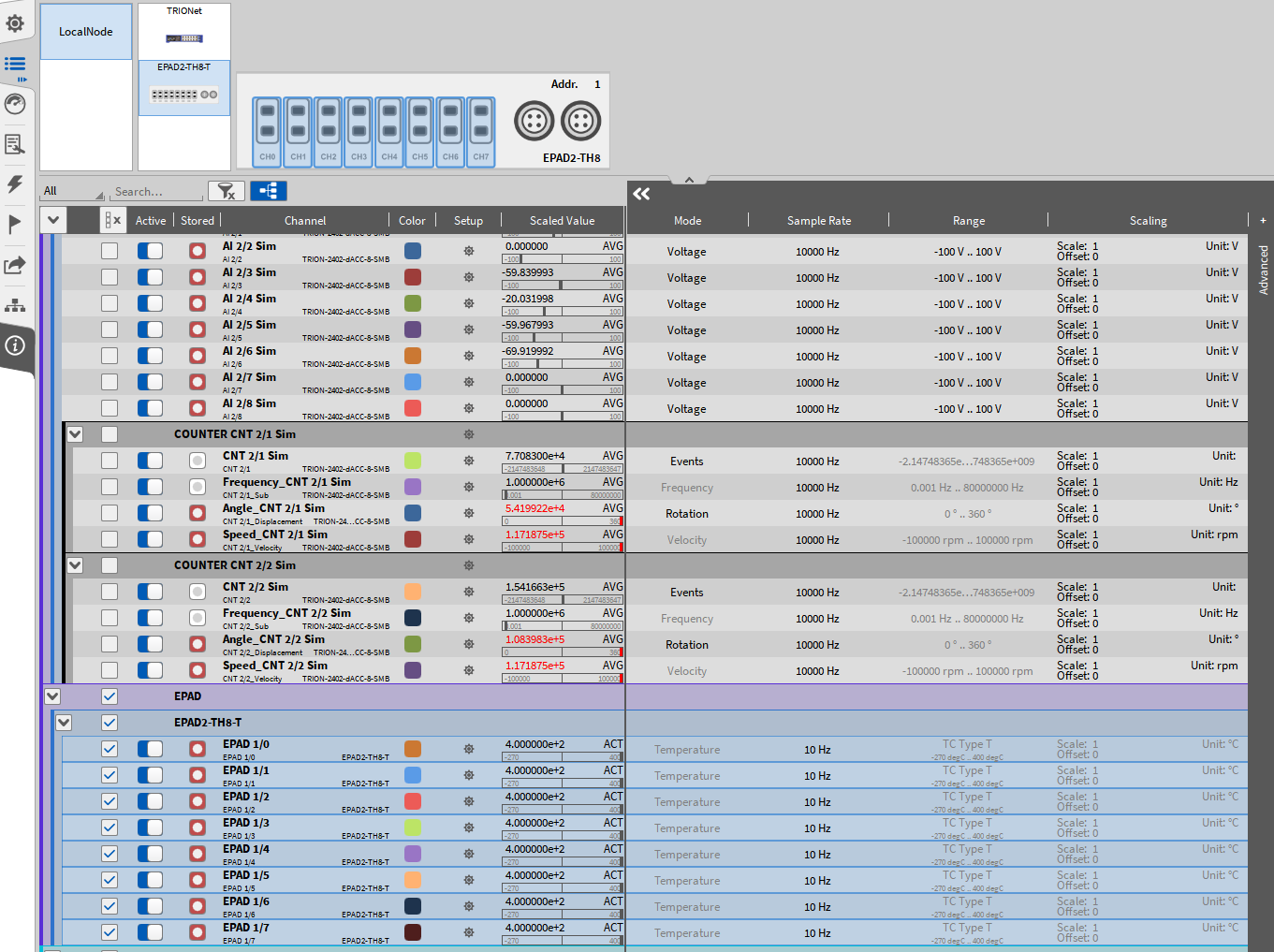
Fig. 61 EPAD channel list
Note
If no thermocouple is connected to an EPAD-channel, the value 1372.0 °C (2501.6 °F) is displayed.
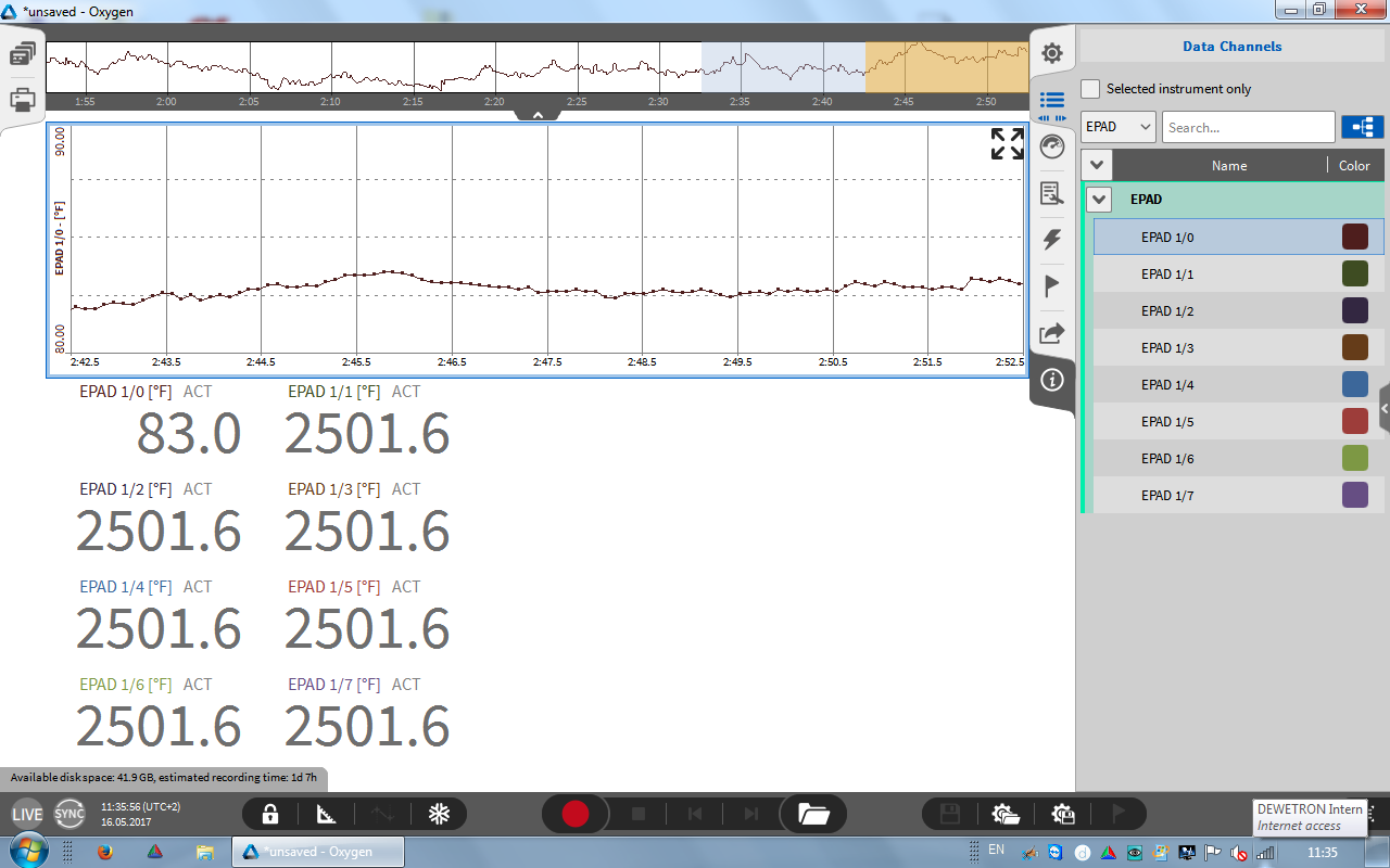
Fig. 62 Displaying EPAD2 data
Using XRs / CPADs with OXYGEN
This section describes the setup process when using CPADs in OXYGEN. The same process is valid for setting up an XR.
For settings up CPADs and decoding their data without the need to load a .dbc file OXYGEN R5.6 (and later) provides a CPAD Decoder plugin. All CPAD types are supported.
This plugin can be used to do the following in OXYGEN: - Change the CPAD module’s Baud rate - Read out module properties - Edit CPAD channel settings - Change CPAD sample rate
For sure, the conventional approach of decoding the CPAD’s CAN data by loading a .dbc file is still supported.
To decode CPAD data with the CPAD Decoder plugin per form the following steps:
Connect the CPAD to the desired CAN port and open its Channel settings in the Channel List (see ① in Fig. 63).
Select the Baud rate of the CPAD (see ② in Fig. 63)
If you don‘t know the CPAD‘s Baud rate change the Baud rates until the Frame Preview shows alternating Message IDs and frames (see ③ in Fig. 63)
Make sure that the CAN bus is terminated with a 120 Ohm resistor or set the internal module termination to True (see ④ in Fig. 63)
When the Baud rate is set up correctly press Add decoder (see ⑤ in Fig. 63)
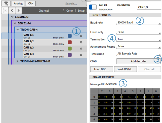
Fig. 63 Adding a CPAD decoder
Alternately, the CPAD decoder plugin can be added by the “+”-button as well. To do so, select the correct CAN-bus, press “+”, choose CPAD Decoder and press Add (see Fig. 64). With the option “Synchronous output channels” ④, the acquired CAN data is forced to equidistant timestamps.
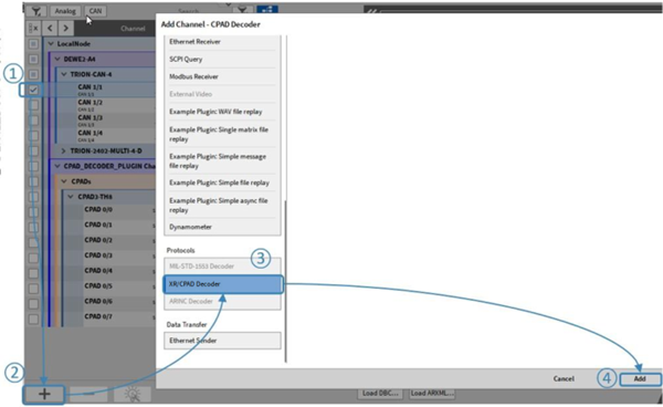
Fig. 64 Adding a CPAD decoder Adding a CPAD decoder (alternate approach)
After creating the CPAD decoder, the detected CPADs and their channel can be found in the channel list (see ① in Fig. 65). If desired, the referring CAN port can be changed (i.e. when a CPAD is connected to a different port) by selecting a different CAN port in ② in Fig. 65. The module baud rate can be changed here as well (see ④ in Fig. 65) in addition to the synchronous timestamp forcing equidistant timestamps if “True” ⑤. Make sure to change the CAN bus baud rate as well to properly receive and decode data in ② of Fig. 63.
Additionally, the configuration of the CPAD / XR can be saved into a DBC-file here (see ③ in Fig. 65).
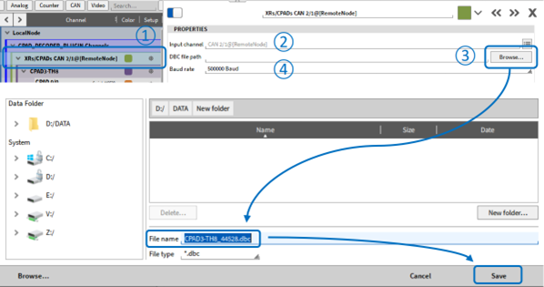
Fig. 65 CPAD decoder settings
Note
If one of several connected modules cannot be found in the list it has most likely a different baud rate that the others. Change the CAN bus baud rate until the missing module is detected and change the module baud rate to the desired baud rate. You can disconnect all modules but the missing module for an easier workflow here.
The CPAD’s specific properties can be found in the CPAD’s individual channel setup (see Fig. 66):
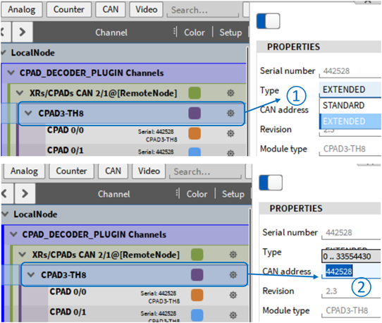
Fig. 66 CPAD specific properties
It is possible to edit the CAN address/ID of the CAN Message sent by the CPAD in decimal form (see ① in Fig. 66).ID Type Extended (by default) or Standard can be selected (see ② in Fig. 66).
The channel settings can be edited in the individual CPAD channel setup (see Fig. 67):
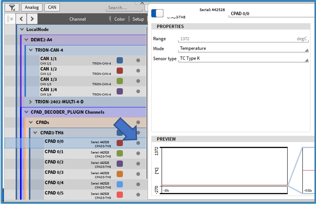
Fig. 67 CPAD channel setting
The CPAD’s sample rate can be changed in the Sample Rate column of the Chanel List (see Fig. 68):
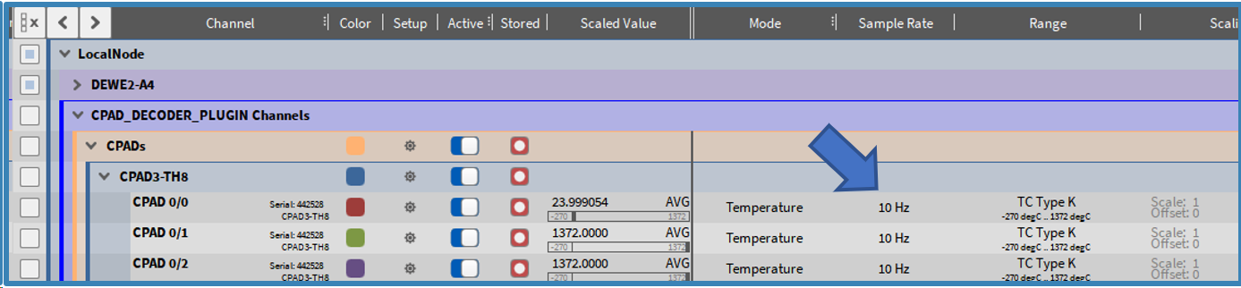
Fig. 68 Changing the CPAD sample rate
Using DAQP/HSI Modules with OXYGEN
Connecting DAQP/HSI Modules via an ORION Card to the Measurement System
DEWE-ORION-xx16-xxx boards
If the DAQP/HSI modules are connected via DEWE-ORION-xx16-xxx boards to the measurement system, go to the DAQ Hardware setup and make sure that the ORIONDAQ Series hardware is enabled as well as the DAQP Series (see Fig. 69) (Changes take effect on application restart) and that the proper driver is installed.
The installer is named DeweDevSetup_x64.exe for 64-bit systems and DeweDevSetup_x86.exe for 32-bit systems and can be found in the folder \files\drivers\2_daqboards\dewetron\orion_driver\DAQ-BOARDS_DRIVER_v2.1.0.0 of the Install Media USB stick which is delivered with the measurement system.
DEWE-ORION-xx22-xxx and DEWE-ORION-xx24-xxx boards
If the DAQP/HSI modules are connected via DEWE-ORION-xx24-xxx or DEWE-ORION-xx22-xxx boards to the measurement system, go to the DAQ Hardware setup and make sure that the ORIONDSA Series hardware is enabled as well as the DAQP Series (see Fig. 69) (changes take effect on application restart) and that the proper driver is installed.
The installer is named DeweDevSetup_x64.exe for 64-bit systems and DeweDevSetup_x86.exe for 32-bit systems and can be found in the folder \files\drivers\2_daqboards\dewetron\orion_driver\DSA-BOARDS_DRIVER_v4.1.0.0 of the Install Media USB stick which is delivered with the measurement system.
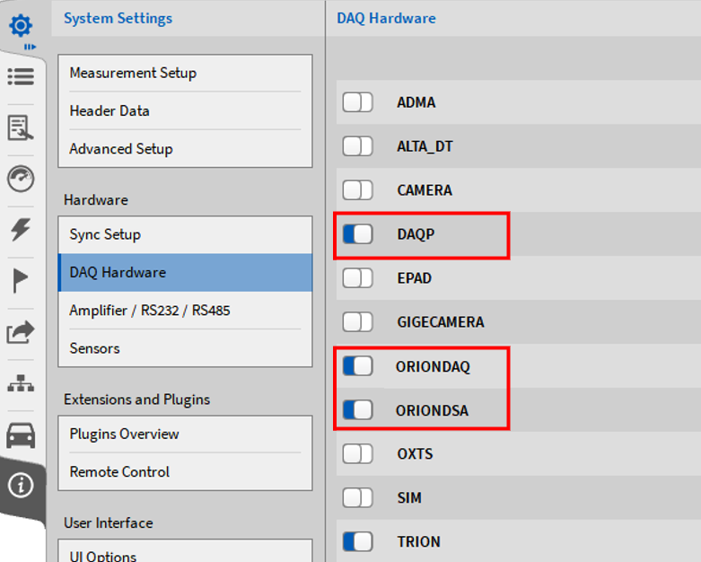
Fig. 69 Enabling the ORION DAQ/DSA Series in the DAQ Hardware setup
Connecting DAQP/HSI modules via a TRION-1802/1600-dLV board
Go to the DAQ Hardware setup in the System Settings and make sure that the DAQP Series and the TRION Series are enabled (see Fig. 70). Changes take effect on application restart.
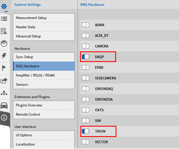
Fig. 70 Enabling DAQP and TRION hardware in the DAQ Hardware setup
Make sure that the driver for the TRION-hardware is installed. The installer is named DEWETRON-TRION-Applications-x64.exe and can be found in the folder \files\drivers\2_daqboards\dewetron\trion_driver\DEWETRON TRION Rx.x of the Install Media USB stick which is delivered with the measurement system.
If the driver was installed correctly, the DEWE2 Explorer will be available in Windows start menu.
Programming the modules addresses
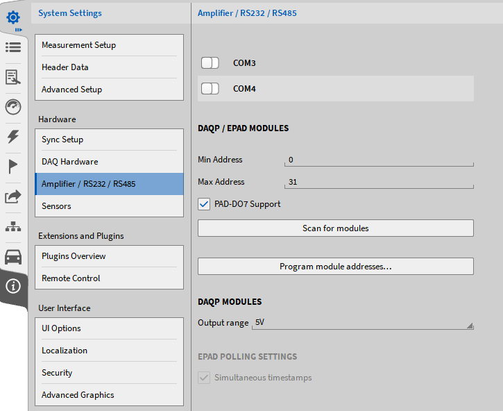
Fig. 71 Programming module addresses
Enable the Serial Port(s) on which the modules are connected (see ① in Fig. 71).
Select the proper output range of the module in the Advanced Setup (see Advanced settings).
Click on Program module addresses (see ② in Fig. 71).
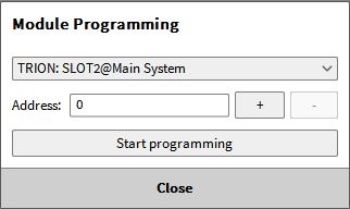
Fig. 72 Module programming UI
Select the proper Serial Port and click on Start programming (see Fig. 72). If the modules are connected to several serial ports, the Programming must be repeated for each serial port. The following window will appear:
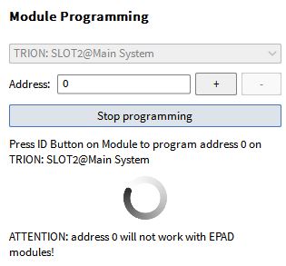
Fig. 73 Programming the module addresses
Keep the ID button of the DAQP/HSI module pressed until the Address increases. Repeat that procedure for all DAQP modules. After finished, press on Stop programming and close the window by pressing Close & Scan (see Fig. 74) or start the programming for a further Serial Port
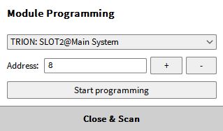
Fig. 74 Finish the module programming
OXYGEN will now read the actual settings from the DAQP modules and write them to the channel settings in the software
Note
A click on Scan for modules will only scan for modules that have already been programmed and store the actual module settings
The modules will appear in the Channel List now and the settings can be edited.
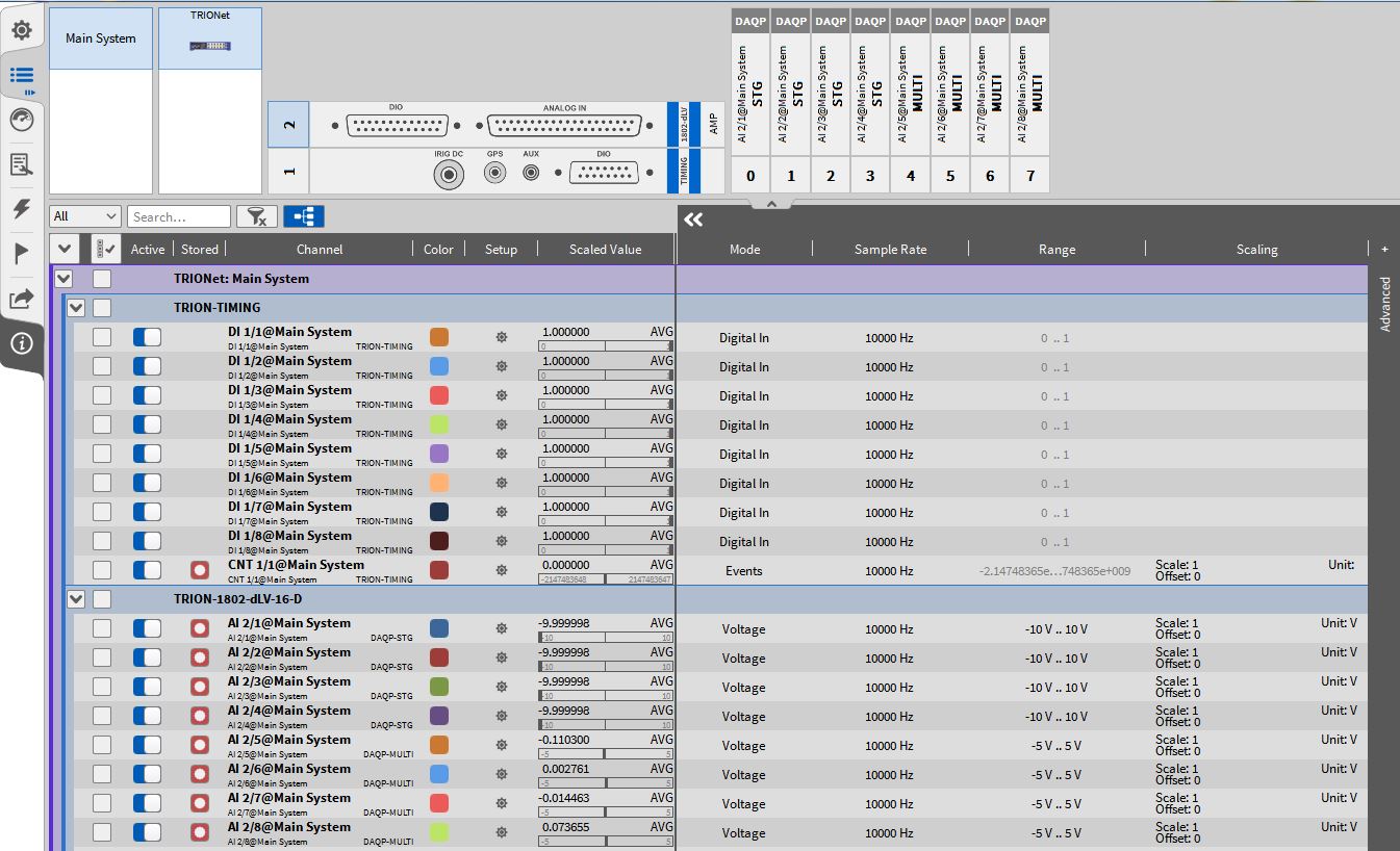
Fig. 75 DAQP/HSI modules in the Channel List connected via TRION-1802-dLV
Note
Counter and Digital channels of an ORION card are not supported by OXYGEN.
CAN channels of an ORION card are supported by OXYGEN and can be found at the bottom of the Channel List.
CAN-FD & FlexRay
Using CAN-FD is possible via NEXDAQ, the TRION3-CAN-FD module or a software option and using external hardware in the form of a vector box.
CAN-FD via NEXDAQ or TRION3-CAN-FD
Switch to the channel list and enable the CAN channel and set the appropriate baud rate high and baud rate (low). In case of using CAN mode, set the same baud rate for both.
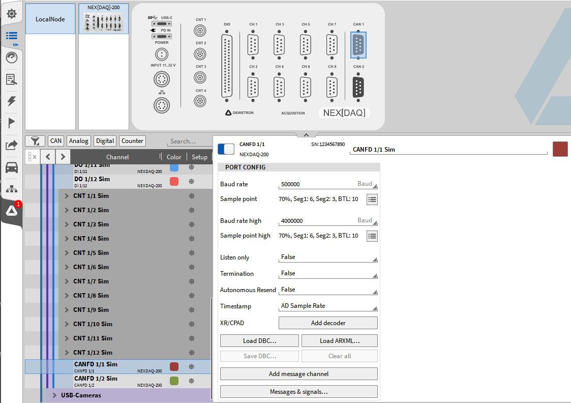
Fig. 76 CAN-FD channels with the TRION3-CAN-FD module
To switch between protocols, create a message and change the protocol between CAN, J1939 and CAN-FD.
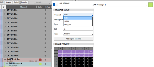
Fig. 77 Change protocol between CAN, CAN-FD and J1939
CAN-FD & Flexray in OXYGEN via Vectorbox
Note
CAN-FD data acquisition is an optional feature and requires a separate license for OXYGEN.
CAN-FD data streams can be acquired with OXYGEN if and only if the following hardware is used in combination with OXYGEN:
Vector VN1610 (2 CAN-FD interfaces)
Vector VN1630 (2 CAN-FD interfaces)
Vector VN1640 (4 CAN-FD interfaces)
FlexRay data streams can be acquired with OXYGEN if and only if the following hardware is used in combination with OXYGEN:
Vector VN7610 (1 FlexRay interfaces)
The hardware must be connected via USB to the measurement system where OXYGEN is running on.
Besides CAN-FD data acquisition, the VN16x0 interfaces can also be used to acquired conventional CAN-Data streams (up to 1 MBaud).
In addition, it can also be used to transmit data over CAN. This is an additional optional feature and requires a separate license. For details, refer to CAN-OUT - transmitting OXYGEN data via CAN:.
To use one the above-mentioned CAN-FD and FlexRay interfaces, proceed the following steps:
Run the latest Vector_Driver_Setup which is available on the Vector homepage and delivered together with the Vector hardware.
Select the drivers of the hardware device that shall be used and run the installation procedure (see Fig. 78).
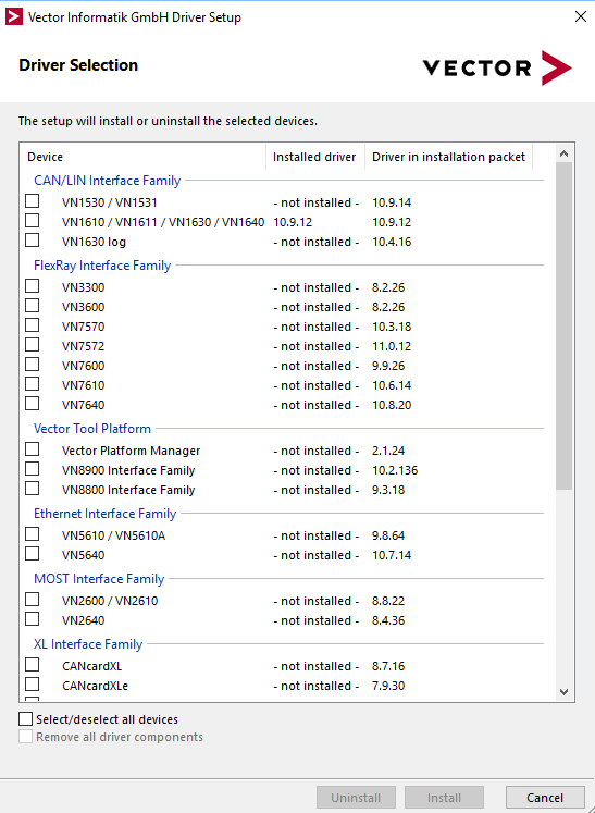
Fig. 78 Vector driver selection
After the installation is finished, connect the Vector device to the measurement system if not already happened.
Open OXYGEN and go to System Settings DAQ Hardware and make sure that VECTOR Hardware is enabled (see DAQ Hardware)
Note
If VECTOR is written in red (see Fig. 80), your currently installed OXYGEN license does not support Vector CAN-FD hardware (see Fig. 80). Contact our support team for help and also for compatible drivers.
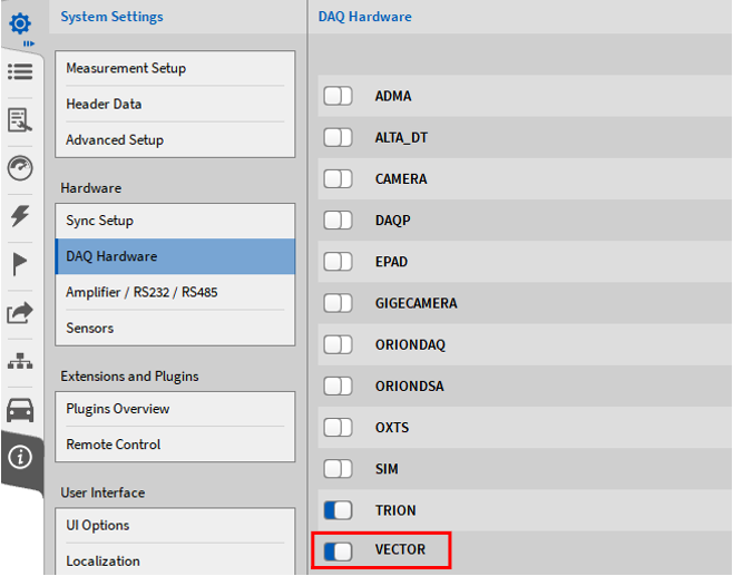
Fig. 79 Enabling Vector CAN-FD hardware in OXYGEN

Fig. 80 Missing Vector CAN-FD hardware license
Changing the settings in this menu, requires an OXYGEN restart.
Note
If the connection between the Vector hardware device and the measurement system should fail during the operation (i.e. the USB cable is unplugged), OXYGEN must be restarted after solving the connection problem to enable the CAN-FD data acquisition again.
Channel Setup for CAN-FD channels
Open the OXYGEN Channel List. The Vector Hardware channels will be visible in the section VNxxxx of the Channel List (marked red in Fig. 81).
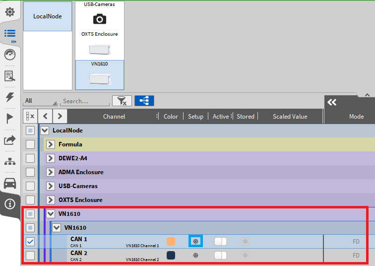
Fig. 81 Channel List with Vector VN hardware included
Click on the Gear button to open the Channel settings (marked blue in Fig. 81). The Baud rate and additional settings can be changed here and the dbc-file can be loaded (see Fig. 82).
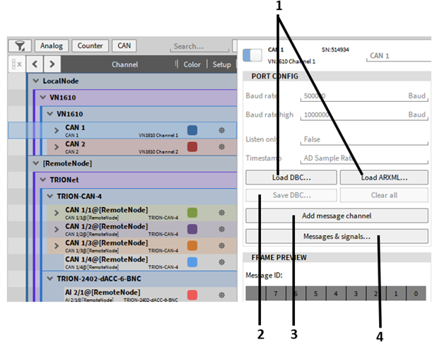
Fig. 82 CAN-FD channel settings
Nr. |
Feature |
Description |
|---|---|---|
1 |
Load a dbc/arxml file |
After the dbc/arxml file has been loaded, a channel selection dialog opens (see Fig. 86), in which the CAN FD messages and channels can be selected. It is possible to select single channels, messages or all channels and messages. |
2 |
Save DBC file |
If all CAN messages and signals have been configured, a *.dbc file can be created via Oxygen. After pressing “Save DBC” a window opens to define the save path and the file name. |
3 |
Add message channel |
After pressing the button, a new message channel is added automatically. Additional CAN signals can be defined for this channel (see numref:CAN_messages_signal_1). |
4 |
Messages and signals |
After pressing, a new window opens for a clearer display of all CAN messages and signals (see Fig. 84). |
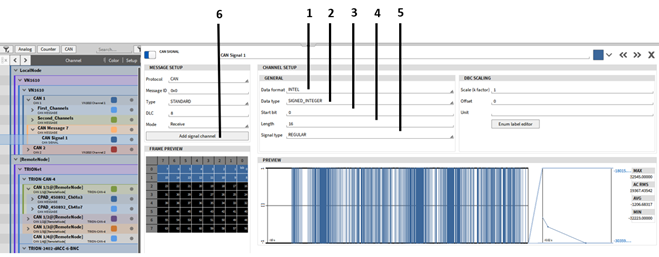
Fig. 83 CAN messages and signal settings (1)
Nr. |
Feature |
Description |
|---|---|---|
1 |
Dataformat |
Selection of the data format. You can choose between INTEL (little-endian) or MOTOROLA (big-endian). |
2 |
Datatype |
Here the data type of the signal is defined. DOUBLE, FLOAT, SIGNED_INTEGER and UNSIGNED_INTEGER are available for selection. |
3 |
Start Bit |
Here the start bit of the respective signal is defined (first bit = 0). |
4 |
Length of the signal |
Here the length of the signal is defined, or the number of bits that represent the signal. |
5 |
Signaltype |
The choices are “REGULAR”, “MULTIPLEXED” and “MULTIPLEXOR”. “REGULAR”: The individual signals within a CAN message are defined based on the start bit and length and are always constant for the CAN message. “MULTIPLEXOR”: The signal is used to define the transmitted signals within the CAN message. The first bits represent the transmitted signals. Thus different signals can be transmitted with a CAN message of the same CAN ID, depending on the “MULTIPLEXOR” value. The “MULTIPLEXOR” value is called MUX ID. “MULTIPLEXED”: Indicates that the signal is defined by the “MULTIPLEXOR”. A multiplexed signal needs to specify its MUX ID. The signal or signals matching the MUX ID will be decoded. |
6 |
Add signal channel |
Additional signals can be added simply by pressing the “Add Signal Channel” button. A new window opens (see Fig. 84) for a better overview of all CAN messages and signals of the selected CAN port. |
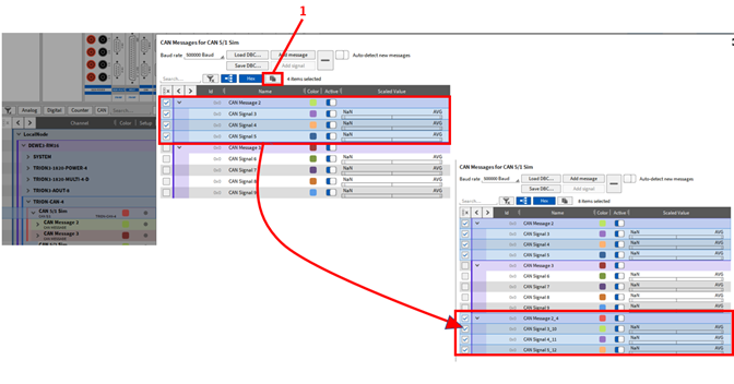
Fig. 84 CAN messages and signal settings (2)
By pressing the button “1” (see Fig. 84), the marked CAN messages and signals are copied and added to the list of existing CAN messages and signals including the settings.
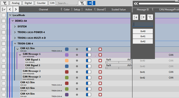
Fig. 85 CAN messages ID
In the channel list it is also possible to filter the available CAN message IDs to get a better overview or to display only the CAN messages that are needed for the current application (see Fig. 85)
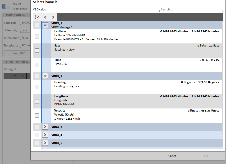
Fig. 86 Channel Picker dialog
To select additional channels later on, just reload the dbc-file and pick more channel In the channel picker dialog. The Clear all (Fig. 82) buttons deletes the current channel selection.
After loading the channels from the dbc-file, an arrow positioned left to the Channel name will appear. A click on the Arrow will expand the CAN-FD channel list and show the individual CAN-FD messages including their channels (see Fig. 87).
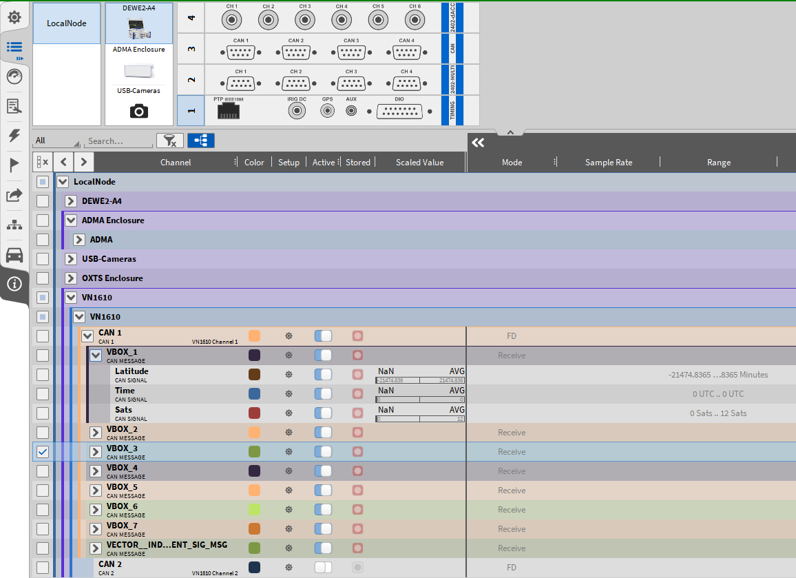
Fig. 87 CAN-FD channel list in OXYGEN
Note
For more details about CAN-channels in OXGYEN, refer to CAN Input Channels.
Offline decoding of CAN-FD:
It is possible to add additional channels that shall be decoded during the data analysis. Therefore, open the respective CAN-FD port in the channel list and load the dbc-file again. Additional channels can be selected and decoded now.
Note
It is not possible to delete previously recorded and decoded channels from a data file.
CAN-FD Bit Timing - Port Configuration
The CAN-FD Bit Timing option is included since OXYGEN R5.1.1
Note
This is an advanced feature and not intended to be changed for the normal CAN-FD data acquisition.
Different Bit Timing per Sample point can be selected from a predefined table for the baud rate and the baud rate high in the CAN-FD port configuration:
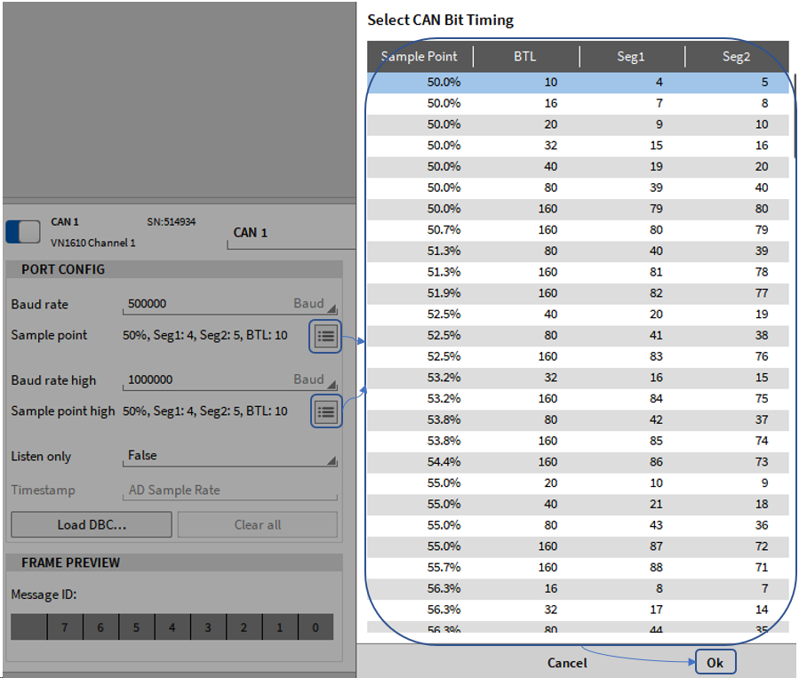
Fig. 88 CAN-FD Bit Timing selection
CAN-FD Bit Timing - CAN(-FD) samplepoint
The sample point is the location (percent value), inside each bit period where the CAN controller looks at the bus state to determine if it is a logic 0 or logic 1. OXYGEN allows this point to be configured. It is specified as a percentage from the start of the bit period.
The location of the sample point is a trade-off. An early sample point decreases the sensitivity to oscillator tolerances and allows lower-quality oscillators. A late sample point allows for a longer signal propagation time and therefore a longer bus. A later sample point is useful for non-ideal bus topologies.
Due to the two different baud rates CAN-FD uses, the importance of a correct sample-point-setup along all bus-participants is of increased importance. (http://www.bittiming.can-wiki.info/ and https://kb.vector.com/entry/861/)
OXYGEN choses a default sample-point of 70 %, (please note, that all bus-timings are realized in hardware by integer clock-dividers for the base clock of 80 MHz, not every value can be met exactly)
As mentioned above, the sample point is a trade-off, and thereby different buses may be designed to choose a sample-point-setup different to 70 % to satisfy other constraints or needs.
To allow interaction with a wide range of such busses, OXYGEN allows to configure the sample-point for both baud rates.
Generally, a range of 50 % ≤ sample-point ≤ 97.0 % is considered, in 0.1 % steps.
Due to the clock-generation and segment-timing generation using integer clock-dividers with their own constraints not all values are possible for all baud rates.
Note
For details about the constraints of the parameters see XL_Driver_Library_Manual_EN.pdf
On the other hand, this also means, that various equal sample-point-values can be achieved by several different divider-settings.
Eg. 70.1 % @ 500 kBd can be achieved by 5 different divider settings.
Additional to the sample-point the time-quanta-values for 2 relevant segments are represented in the table. This allows easy matching if the time-quanta-values of the bus-participants is known.
All lengths in timequanta (the smallest unit for all configuration values)
BTL denotes the length of the Propagation_Delay_Segment + Phase_Segment_1 + Phase_Segment_2 + 1
Seg1 denotes the length of Propagation_Delay_Segment + Phase_Segment_1
Seg2 denotes the length of Phase_Segment_2
The samplepoint is [(Seg1 + 1) / BTL]
If the baud rate changes, the bit timing parameters (sample point and prescaler) will automatically be adjusted to the best matching values.
Channel Setup for FlexRay channels
Open the OXYGEN Channel List. The Vector Hardware channels will be visible in the section VNxxxx of the Channel List (marked red in Fig. 89).
Fig. 89 Channel List with Vector VN hardware included
Click on the Gear button to open the Channel settings (marked blue in Fig. 89). Click on the Load Fibex… button to select the proper fibex-file (see Fig. 90).
The fibex file must be compatible with Fibex 2.0 to 4.1.2 Standard for description file (ASAM MCD-2 NET)
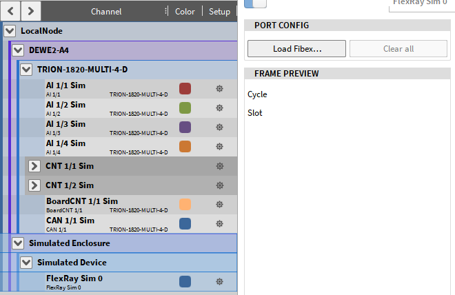
Fig. 90 FlexRay channel settings
After loading the fibex-file, a Channel picker dialog (see Fig. 91) will open to select the channels from the fibex file that shall be decoded during data acquisition. It is possible to select only certain channels and messages or all channels.
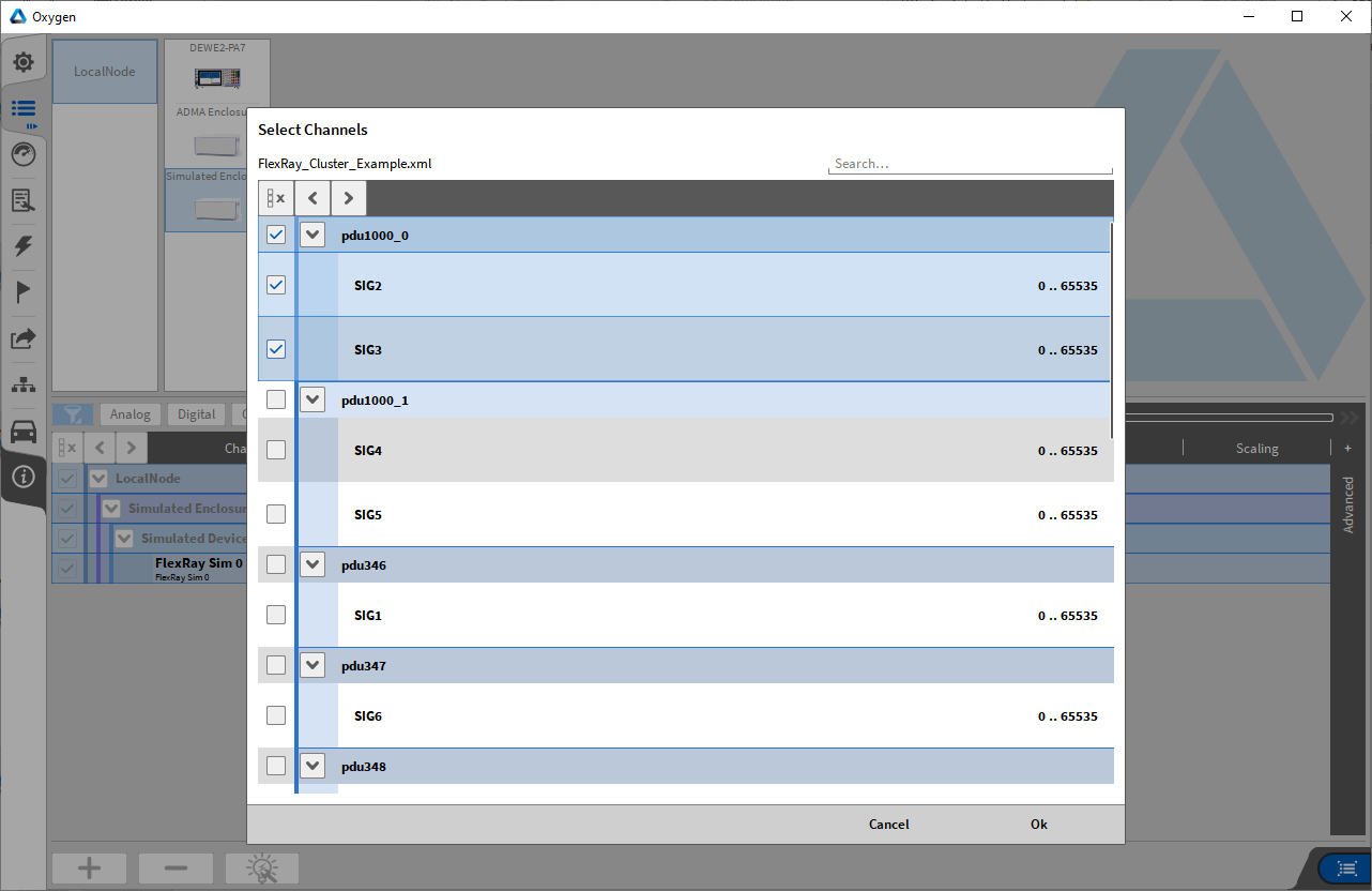
Fig. 91 Channel Picker dialog
To select additional channels later on, just reload the fibex-file and pick more channel In the channel picker dialog. The Clear all (Fig. 90) buttons deletes the current channel selection.
After loading the fibex-file, an arrow positioned left to the Channel name will appear. A click on the Arrow will expand the FlexRay channel list and show the individual FlexRay messages including their channels (see Fig. 92).
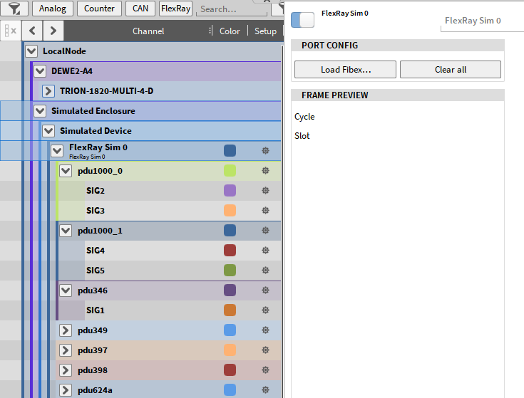
Fig. 92 FlexRay channel list in OXYGEN
Offline decoding of FlexRay:
It is possible add additional channels that shall be decoded during the data analysis. Therefore, open the respective FlexRay port in the channel list and load the fibex-file again. Additional channels can be selected and decoded now.
Note
It is not possible to delete previously recorded and decoded channels from a data file.
Limitations of FlexRay in OXYGEN:
No support of ARXML (AUTOSAR XML) description files
No support of Multiplexed Frames
No bus settings possible – Auto Detection Enabled
No support of STRING channels
No support of different scaling types of one signal depending on range