Measurement settings
The Measurement Settings menu contains all settings which apply to a measurement itself and must be stored in a setup file. The different sections will be explained in the following chapters. To jump to the system options settings, click on the link Jump to system options, seen in Fig. 93.
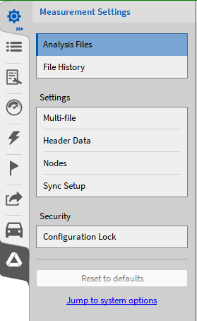
Fig. 93 Measurement Settings section
Note
A single click on any menu button will show a small view of the menu that contains the most important functionalities and information. Keeping the left mouse button on the menu button pressed and moving the mouse to the opposite side of the screen will expand the menu to the full screen and show all options.
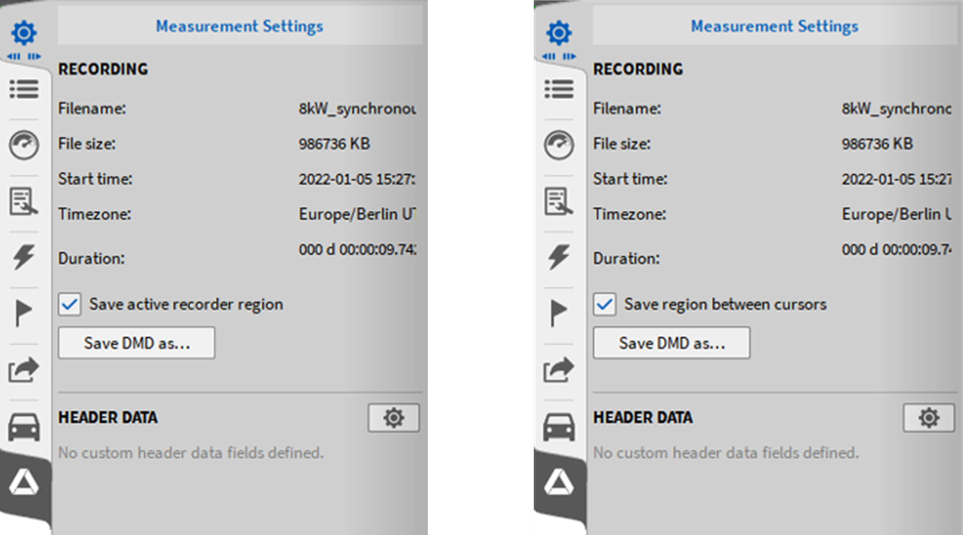
Fig. 94 Measurement Settings in OXYGEN viewer
Opening the small sidebar measurement settings menu of a recorded file in OXYGEN viewer enables the Save DMD as… button. Here it is possible to save only a time slice of the measured data. For more information see Export active recorder region or between cursors.
All settings can be reset by clicking on the button Reset to default, on the left seen in in Fig. 95.
The content of the individual submenus will be explained in the following sections in detail.
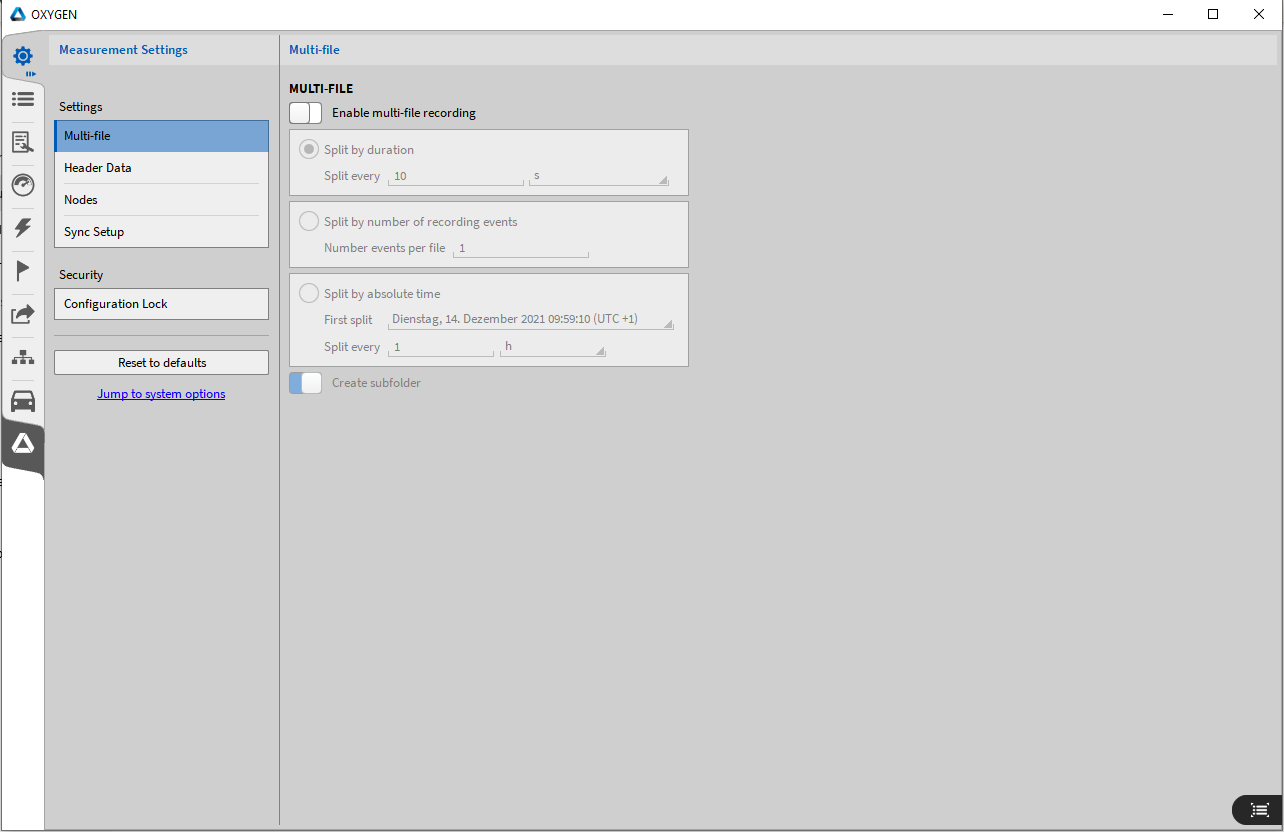
Fig. 95 Measurement Settings menu
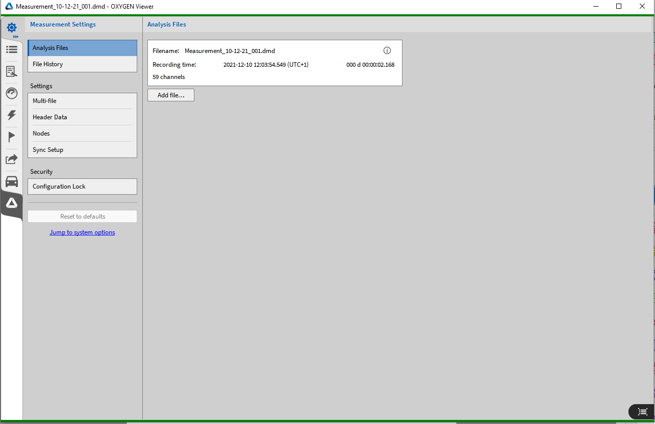
Fig. 96 Measurement Settings menu in PLAY Mode
Functions in PLAY mode
Analysis Files
This section is only available in PLAY mode, i.e. only when a measurement file is opened with OXYGEN, as seen in Fig. 96.
It shows some information about the currently opened measurement file. By clicking on the button Add file… multiple files can be opened. For more information, refer to Opening multiple data files.
File History
This section is only available in PLAY mode, therefore only when a measurement file is opened with OXYGEN, as seen in Fig. 96.
In this section it is possible to apply changes made to a measurement file in the post-processing to other files. For more information, refer to Batch processing.
Settings
Multi-File
Especially during long measurement campaigns, it might be useful if data is not stored to one single file but to several individual files. Among others, this mechanism allows the user to analyze and post-process data from the beginning of the measurement while the measurement itself is still running. This mechanism is called multi-file recording.
If multi-file recording is enabled, OXYGEN supports three different ways to split files:
Split by duration
Split by number of recording events
Split by absolute time.
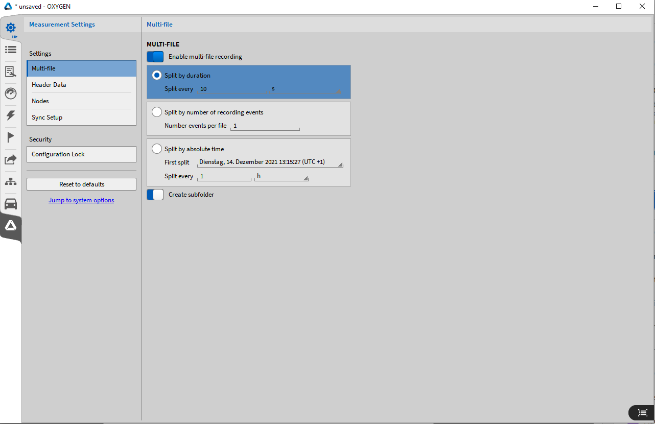
Fig. 97 Multi-File recording settings
Multi-file recording
File names
Multi-file recordings are stored in a separate folder per default, which has the same name as the first multi-file. For more details about the file name pattern see Storing and File name.
To deactive the creation of a subfolder for multi-files, deactivate the slider in the multi-file settings (see Fig. 97). A separate multi-file counter (00x) is used if the individual file names are identical. With the optional text File Start in the Time placeholder, the timestamp of the recording start of each multi-file recording can be used.
Examples
#{Date, Local}_#{Number, Session}
The session counter is 3. Therefore, the multi-file recordings will have the following names: 20210503_003_001, 20210503_003_002, 20210503_003_003 etc.
#{Time, File Start, “hh-mm-ss”}
The multi-file recordings will have the following names: 09-55-29, 09-55-39, 09-55-49 etc.
Split by duration
If split by duration is selected, OXYGEN stores data automatically to a new file if the defined time interval is exceeded: A new data file will be created after 10 s, 2 0s, 30 s etc, overall recording time. The minimum time interval is 10 seconds.
Special case
Split by Duration in combination with enabled event based waveform recording and disabled User Reduced Statistics recording (see Triggered Events). With this combination, it can happen that no data is stored to a multi-file part. The following cases might appear:
No data recording after arming the Trigger: If it takes a certain time after arming Trigger and the first occurring recording event, the time between arming the Trigger and the first occurring recording event will be rejected and the ‘0s’ position will be shifted to the Arm Trigger position to the first occurring recording event. Thus, the first data file begins not at the position the Trigger is armed but at the position the first recording event occurs. The following Fig. 98 will illustrate this case:
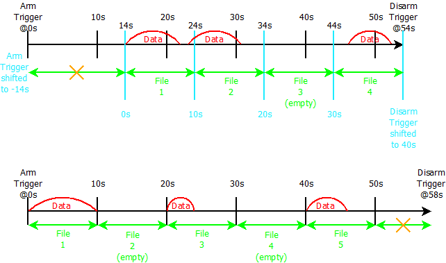
Fig. 98 Special case 1 for multi-file recording; split duration: 10s
No data recording between two recording events: If the time between two occurring recording events is longer than the specified Split time interval, an empty data file created. (see File 3 in Fig. 98)
No data between the last occurring recording event and disarming the Trigger: If it takes a certain time between the last occurring recording event and disarming the Trigger, the time within will be rejected and no new data file will be created. The following Fig. 99 will illustrate that case. This is also the reason why the Split Stop/Start Marker is only created retroactively if a new recording event occurs and not at the exact time the split duration is exceeded.
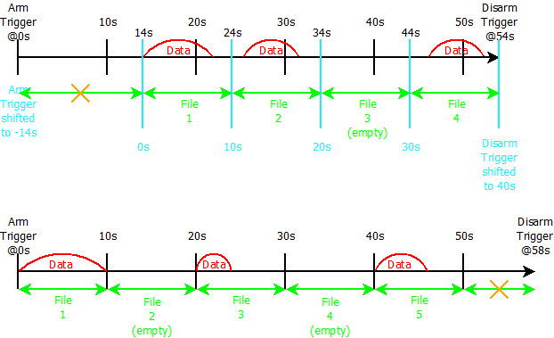
Fig. 99 Special case 2 for multi-file recording; split duration: 10s
Note
If User Reduced Statistics recording is enabled for the upper explained special case, this special case will not be applied, because (statistics) data will be recorded continuously.
Split by number of recording events
If split by number of recording events (see ③ in Fig. 97) is selected, OXYGEN creates a new data file if the defined number of recording events is reached. I.e. in the example of Fig. 97, a new data file will be created after the 2nd, 4th, 6th, … recording event is terminated.
Special Case
If Split by number of recording events is used in combination with a pre-recording time which lasts back to the recording event that occurred before, both recording events will be regarded as one entire recording event, because they are connected by the pre-recording time. The following will illustrate this case for a recording split after two events:
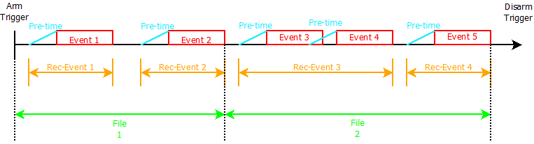
Fig. 100 Special Case 3 for multi-file recording; Split after 2 recording events
Note
The DejaView™ functionality (see DejaView™) is applicable during multi-file recording as well. The instant of time a new data file is created is visible in the event List (see Event List) as Split Start and Split Stop marker (see Fig. 101).
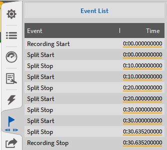
Fig. 101 Split Start and Split Stop Marker
Split by absolute time
If split by absolute time (see ④ in Fig. 97) is selected, OXYGEN stores data automatically to a new file after every defined time interval. The OXYGEN Acquisition Time is used as the reference time. The first split can be selected using the popup calendar.
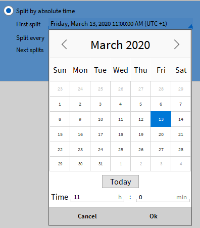
Fig. 102 Pop-up to select the first split
The files can be split after minutes, hours or days. The minimum interval for a split is one minute. After selecting the interval, a small preview of the next splits is shown in the settings in the multi-file section, also shown in Fig. 103. In that way the user can check if the settings are right.
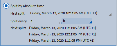
Fig. 103 Split options and split preview for split by absolute time
Special case
Split by absolute time in combination with enabled event based waveform recording and disabled User Reduced Statistics recording (see Triggered Events).
With this combination, it can happen that no data is stored to a multi-file part. The following cases might appear:
No data recording after arming the Trigger
If it takes a certain time after arming Trigger and the first occurring recording event, the first file split will also occur with the first occurring recording event. Thus, the first data file begins not at the position the Trigger is armed but at the position the first recording event occurs. The first file can, therefore, be shorter than the defined interval. The next splits are done correctly according to the defined interval as shown in the split preview. This case is shown in Fig. 104.
No data recording between two recording events
If the time between two occurring recording events is longer than the specified Split interval, an empty data file will be created. (see File 4 in Fig. 104)
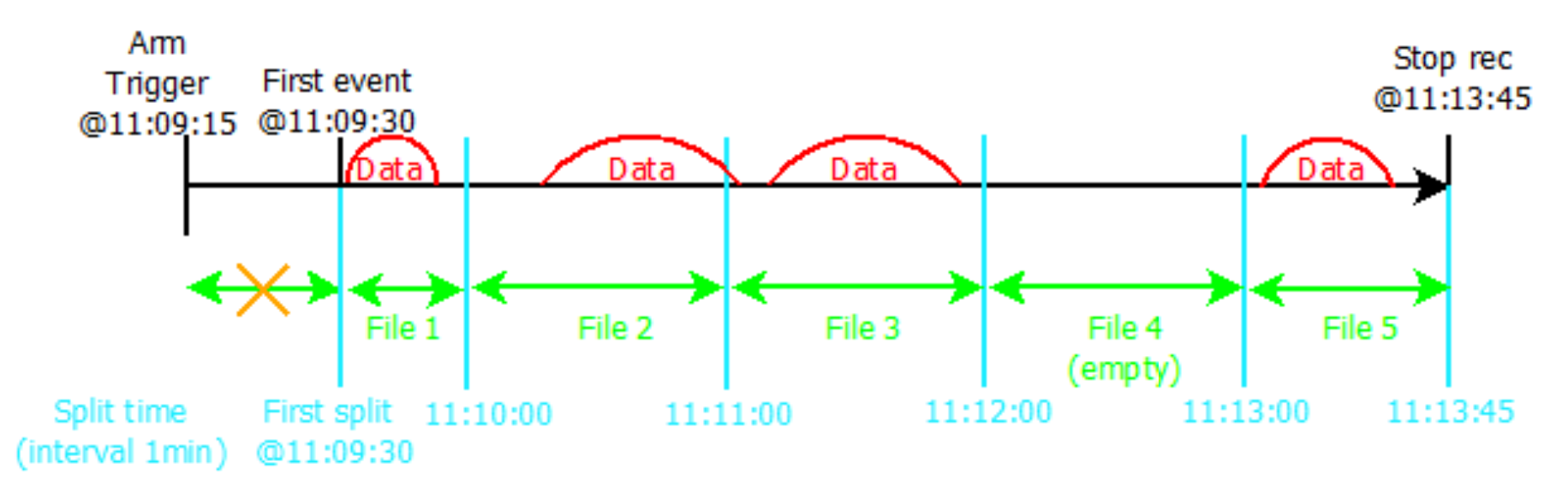
Fig. 104 Special case 1 for multi-file recording; Split by absolute time; interval: 1 min
No data between the last occurring recording event and disarming the Trigger
If no recording event happens after disarming the Trigger, the files will be split and created, nonetheless, according to the defined interval until the stop button is pressed. This case is shown in Fig. 105.
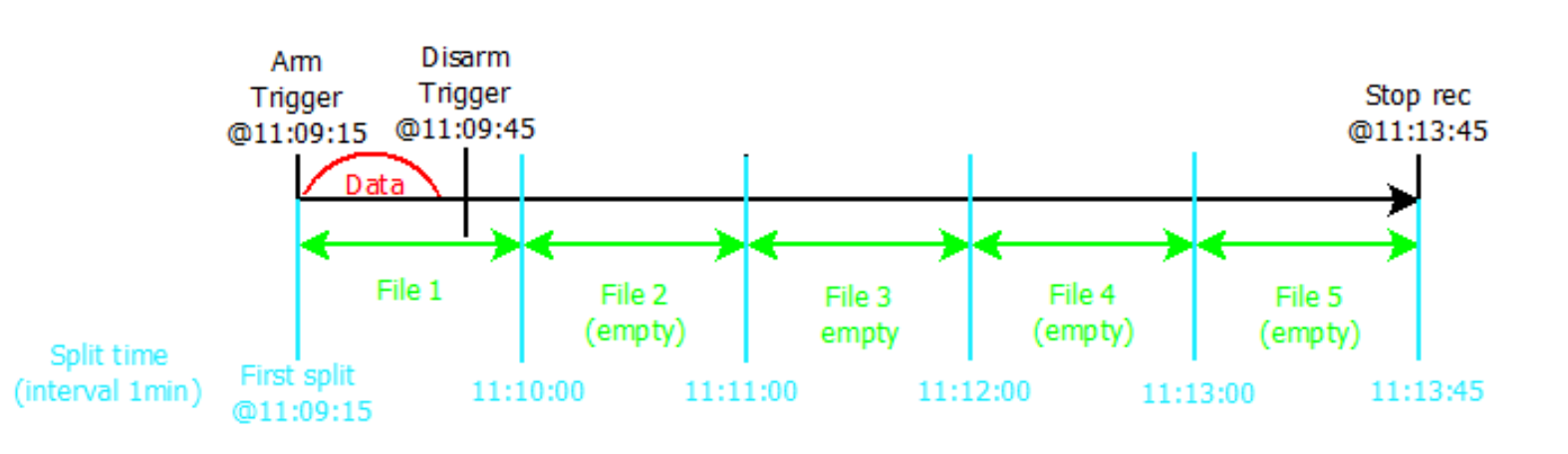
Fig. 105 Special case 2 for multi-file recording; Split by absolute time; interval: 1 min
Note
If User Reduced Statistics recording is enabled for the upper explained special case, this special case will not be applied, because (statistics) data will be recorded continuously.
Splits are only possible on rounded times, therefore only integer numbers can be used, e.g. 1, 2, …, 5 etc. min/h/d. It is not possible to split files every 1.5 hours.
If the first split lies in the past the next splits will be calculated correctly using the actual time.
Split by file size
If Split by file size is selected, OXYGEN stores data automatically to a new file if the defined file size is exceeded. The minimum file size that can be set is 10 MB.
Loading a multi-file
Multi-file parts that belong to the same measurement are stored in the folder of the selected data storing folder (see General settings) or in a separate folder of the selected folder, if the option create subfolder is active. The individual multi-files are enumerated starting with 1.
To load multi-files, click on the Open Data File button (see Fig. 106) and select the desired multi-file data folder. The folder is named to the same manner as data files are named. Thus, a prefix can be freely defined, and the actual date and time is appended automatically to the folder name (see General settings).

Fig. 106 Open data file button
After selecting the correct folder, the single multi-files are shown in a list. The Info tab shows if the selected file(s) is (are) a part(s) of a multi-file-recording and the number of compatible parts selected (see Fig. 107). It is possible to open all parts (see Fig. 108), several parts (see Fig. 109) or only one single part (see Fig. 110) of a multi-file recording. The file selection can be done with the check boxes which are placed left to the file name. If several or all parts are opened, they are displayed in the correct chronological order.
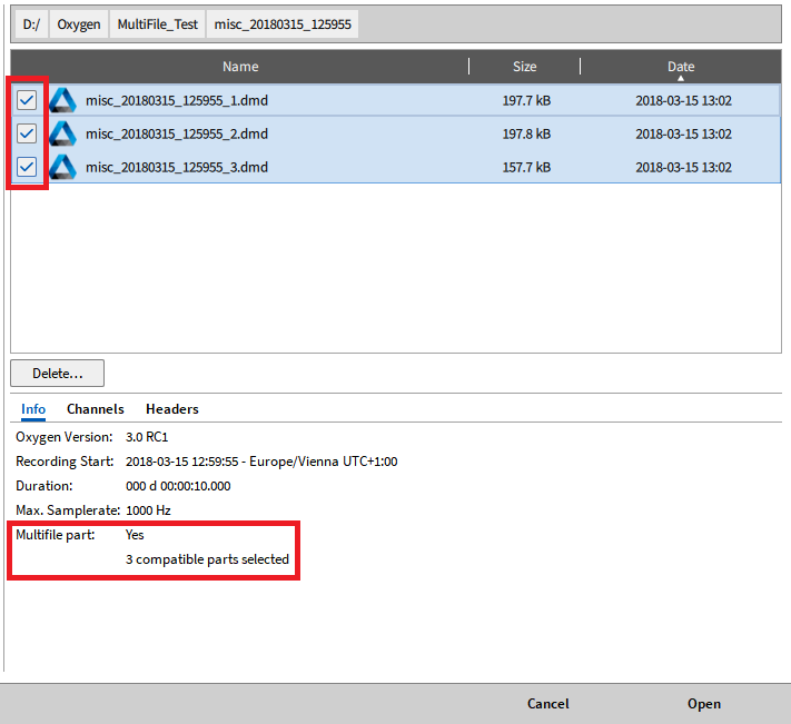
Fig. 107 Opening a multi-file
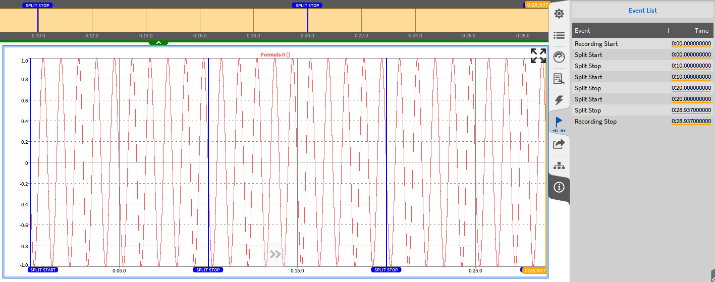
Fig. 108 Opening all parts of a multi-file recording
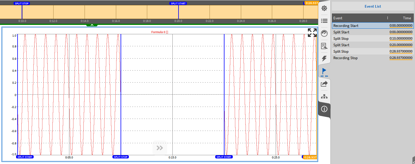
Fig. 109 Opening several parts of a multi-file recording
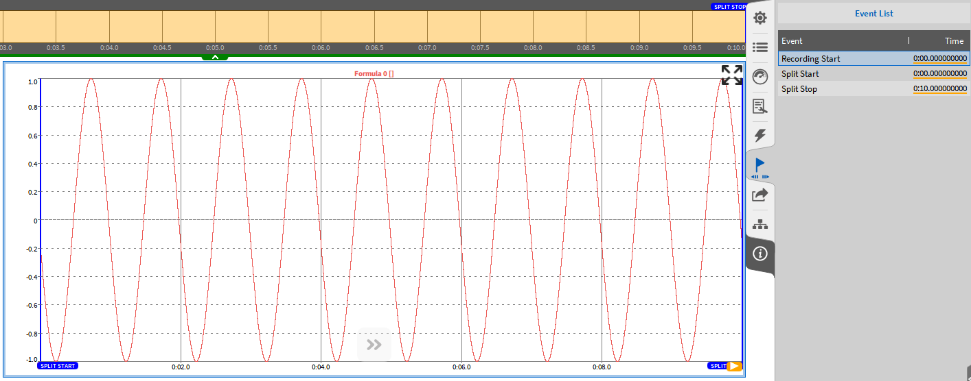
Fig. 110 Opening one part of a multi-file recording
If several parts are selected that are not part of a multi-file recording or don’t belong to the same multi-file recording, an information will be displayed in the Info tab and the Open button will be disabled (see Fig. 111).
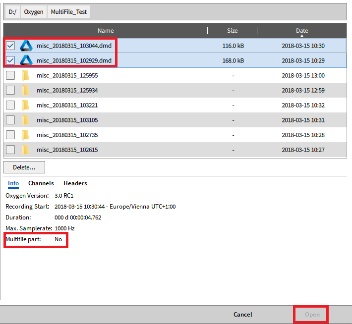
Fig. 111 Selection of non-compatible multi-file parts
If several multi-file parts are opened simultaneously and data shall be exported, data is exported to one file. If data of multi-file parts shall be exported to separate files, the multi-file parts must be opened and exported successively.
Header data
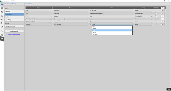
Fig. 112 Header Data – settings
The user can define Header Data here by clicking on the + in the upper right corner or remove it again by clicking on the – behind the respective header information. Two types of header can be defined: Text header and Formula constant header.
Text header
When Header Data is added, a name must be assigned to the certain header information and a description can be added. It can also be selected if the header information shall be prompted at the recording start or at recording stop (see Fig. 113). If this option is selected, the description of each Header Information can be changed there by the certain operator. If Mandatory is selected, the operator must fill in information in the respective Header Description at the recording start or stop. Otherwise the UI cannot be closed.
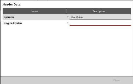
Fig. 113 Header Data UI at the recording start or stop
Formula constant header
In addition, the user can define numerical header which can be further used in a formula for mathematical operations. After defining the header name and value, the header can be found in the math formulas for further processing (see Fig. 114). For details about formulas, refer to Formula channel. The prompt option is not available for numerical headers.
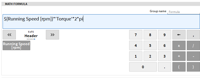
Fig. 114 Processing numerical headers in formulas
When a data or setup file is loaded, the user can also look at the Header Data here to facilitate the search for the correct data file (see Fig. 114).
Selection header
Furthermore, the user can define a selection header which can be used such as a text header, but with multiple manually defined values. As with a text header, the selection can be prompted at the recording start or at recording stop. If this is chosen, a pop-up window will appear on recording start or stop and one value of the selection can be chosen from a drop-down menu.
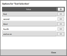
Fig. 115 Options for a selection header
In the options for a selection header a set of values can be defined (see Fig. 115). These can be text or numerical values.
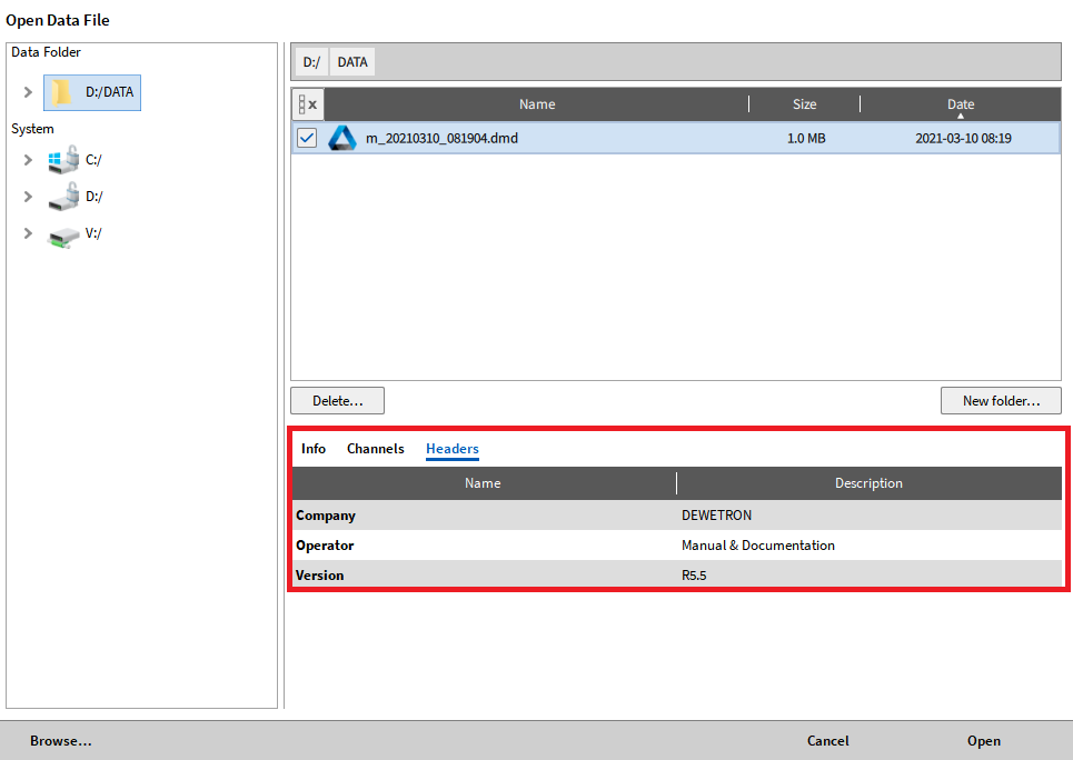
Fig. 116 Header Data information when loading a data file
It is possible to add the Headers in a Text Box (refer to Text instrument) on the measurement screen. Three different procedures exist for adding Headers in a Text Box:
Select the desired Header information at the Header Name in the small view menu of the Measurement settings and add it by Drag and Drop to the Measurement Screen (see Fig. 118).
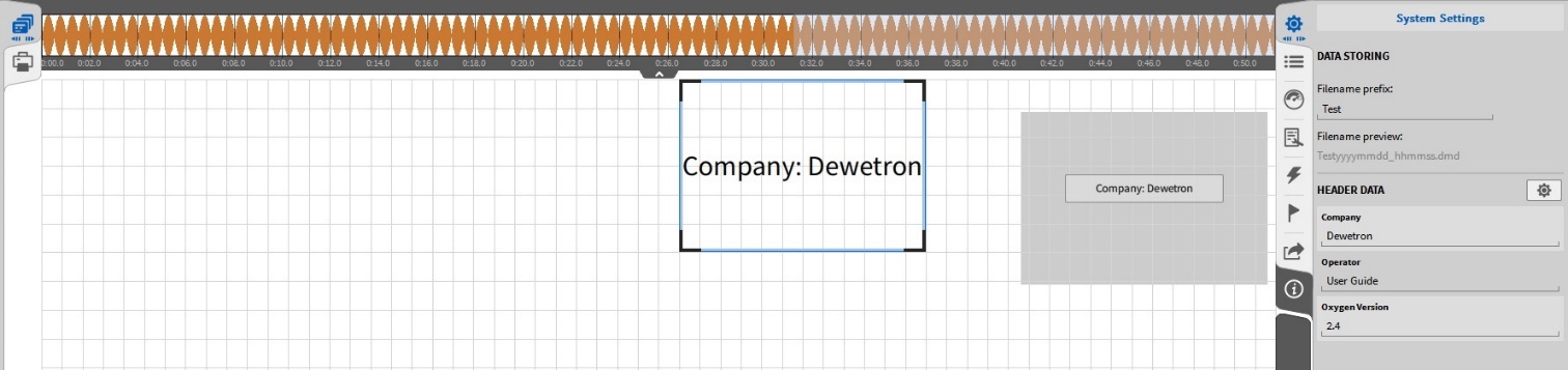
Fig. 117 Adding Header Data via drag and drop from the Measurement settings to the measurement screen
Adding Header Data via drag and drop from the Measurement settings to the measurement screenHeader information can also be added to an existing Text Box by dragging and dropping it into it.
Create a Text Box and go to its Instrument Properties. Created Header Data is there visible, too and can be added to the Text Box via a double click on the individual Header Data or via drag and drop
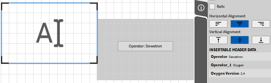
Fig. 118 Adding Header Data via drag and drop from the Text Box Instrument Properties to the measurement screen
Create a Text Box and type in the Header Data Name according to the following syntax: ${Header Data Name} and the Header Data Description will show up in the Text Box (see Fig. 119).
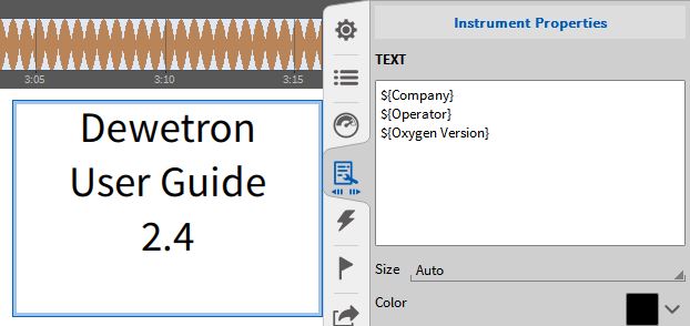
Fig. 119 Adding the Header Description in a Text Box
Nodes
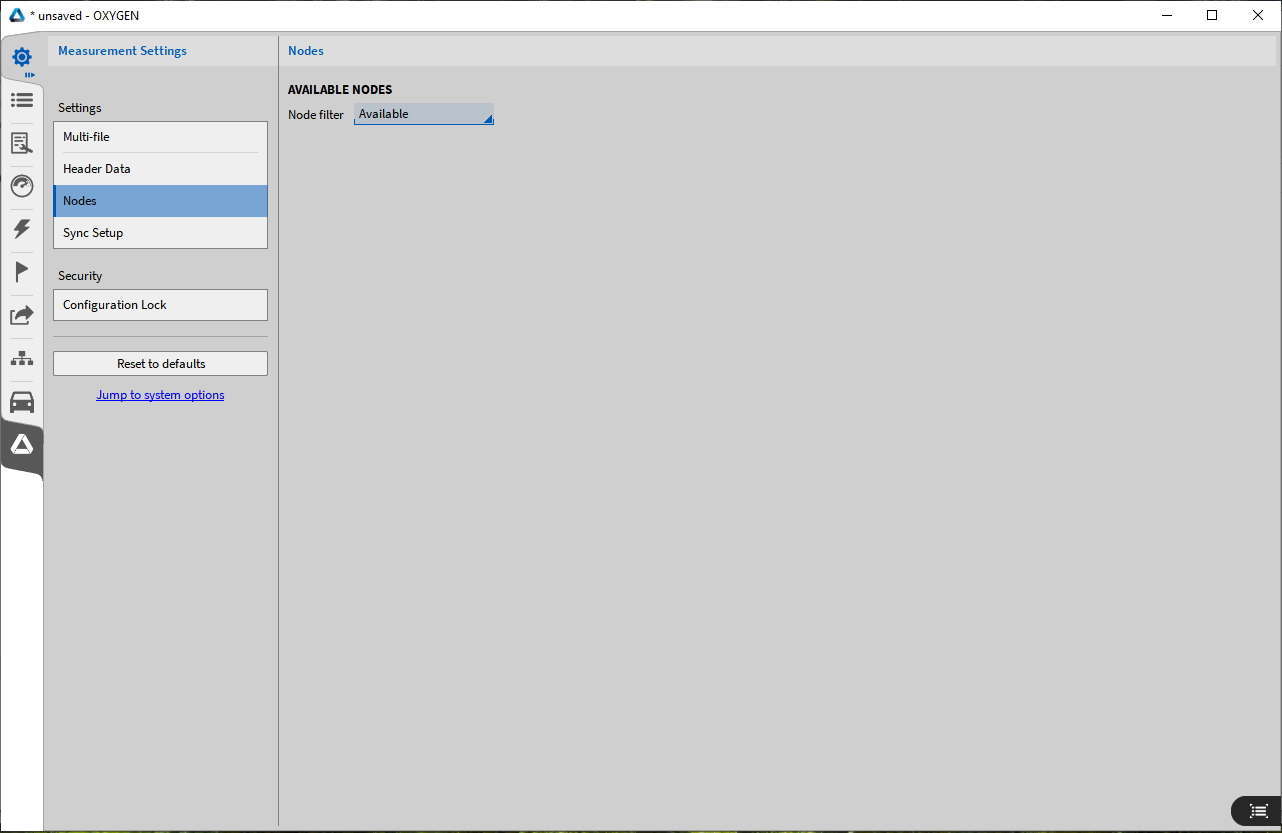
Fig. 120 Nodes menu
Refer to OXYGEN-NET Menu – Nodes for more information.
Sync Setup
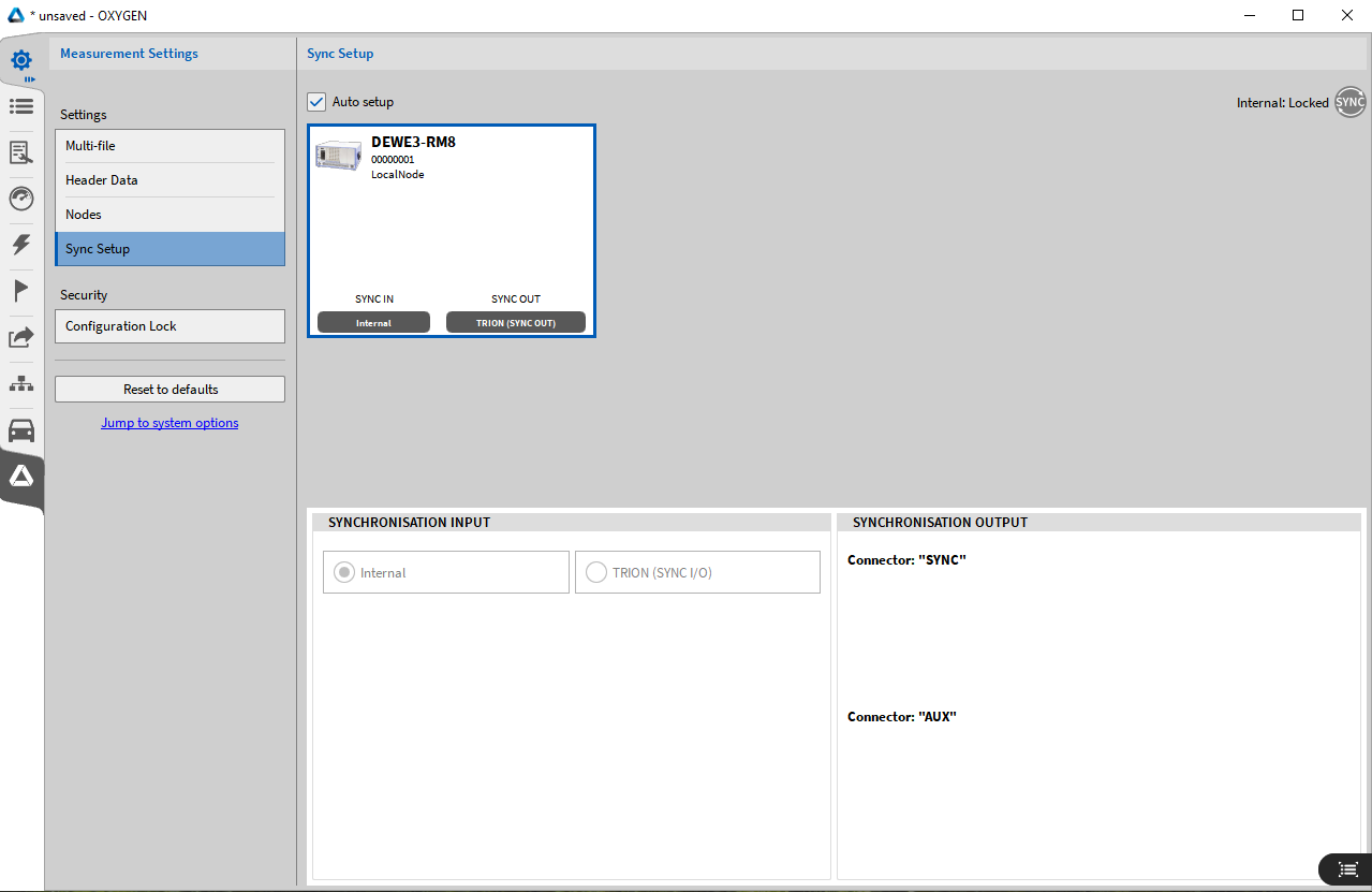
Fig. 121 Sync settings
Refer to OXYGEN-NET menu – Sync for more information.
The following section provides information about the various synchronization options using OXYGEN with TRION hardware or the chassis controller. With DEWE2/3 instruments there is nearly no limit when synchronizing systems with each other. The synchronization of the devices is either done via an Internal 10 MHz clock, TRION-SYNC-BUS (SYNC I/O, SYNC OUT), IRIG, PPS, PTP/IEE1588, or GPS. The synchronization options depend on model and configuration of the DEWE3, instruments.
Fig. 121 displays the Sync Setup settings highlighting:
the SYNCHRONIZATION INPUT section - representing the input configuration of a device on how this instrument “gets” the input signal from any source or “generates” an input signal.
the SYNCHRONIZATION OUTPUT section - representing the output configuration of a device, which defines what kind of signal this instrument routes to the corresponding output to synchronize with the next connected device.
the Sync Status Indicator – providing information about the current synchronization status. For details on the different statuses, see OXYGEN-NET menu – Sync, subsection Sync Status Indicator.
DEWE3 devices can either be synchronized via internal or external timing sources, which can further be forwarded to synchronize additional systems.
Internal Timing Source
Each DEWE3 chassis has an internal 10 MHz clock which is used as the clock source in this particular DEWE3 system. This internal clock is used per default for synchronization. Therefore, the Auto Setup box is checked per default and Internal selected as Synchronization Input Source (see Fig. 122).
Each DEWE3 chassis has an internal 10 MHz clock which serves as the default clock source for that system. Therefore, the Auto Setup box is enabled by default and Internal is selected as the Synchronization Input Source (see Fig. 122). When the internal clock is active, the sync status indicator in the upper-right corner of the synchronization menu appears grey, indicating local synchronization.
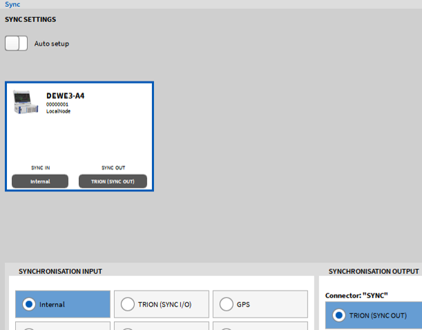
Fig. 122 Sync setup - internal sync clock selected
TRION-SYNC-BUS
In addition, each DEWE3 system can output the 10 MHz clock synchronization signal and forward it to another DEWE3 system via the SYNC In/Out connectors on the system (see Fig. 123). Note that this feature requires the OXYGEN-NET option.
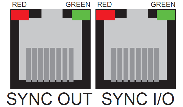
Fig. 123 SYNC IN/OUT connectors of a DEWE3-A4
The SYNC IN connector receives the synchronization signal, while the SYNC OUT connector transmits it. Both connectors are equipped with green and red LEDs that indicate the current acquisition and clock status:
SYNC OUT |
SYNC IN |
|
|---|---|---|
RED (stable) |
Clock detected |
Receiving clock |
GREEN (stable) |
Acquisition running |
Acquisition running |
To synchronize another DEWE3 system via the TRION-SYNC-BUS, the following Sync Settings must be applied to the receiving DEWE3: Uncheck the Auto Setup box and set the Synchronization Input source to TRION (SYNC I/O) (see Fig. 124). By default, TRION (SYNC OUT) is enabled and cannot be disabled.
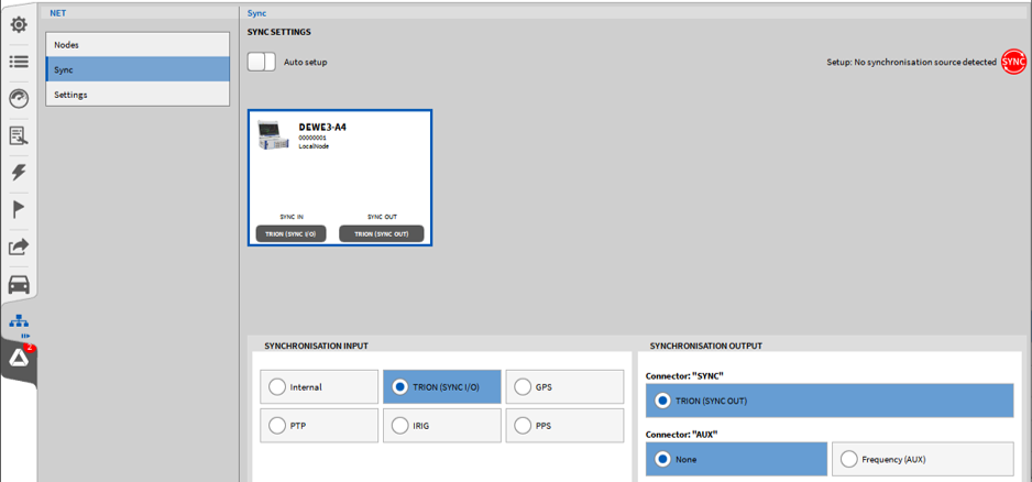
Fig. 124 Sync setup – TRION-SYNC-BUS
External Timing Source
Depending on the hardware used, various external synchronization signals can be used. The following hardware options are available:
Chassis controller of a DEWE3 device
TRION-BASE module
TRION-TIMING module
TRION-VGPS module
Note
The TRION modules must be mounted in the first (Star) slot of the system.
The following Fig. 125 provides an overview about the supported external synchronization:
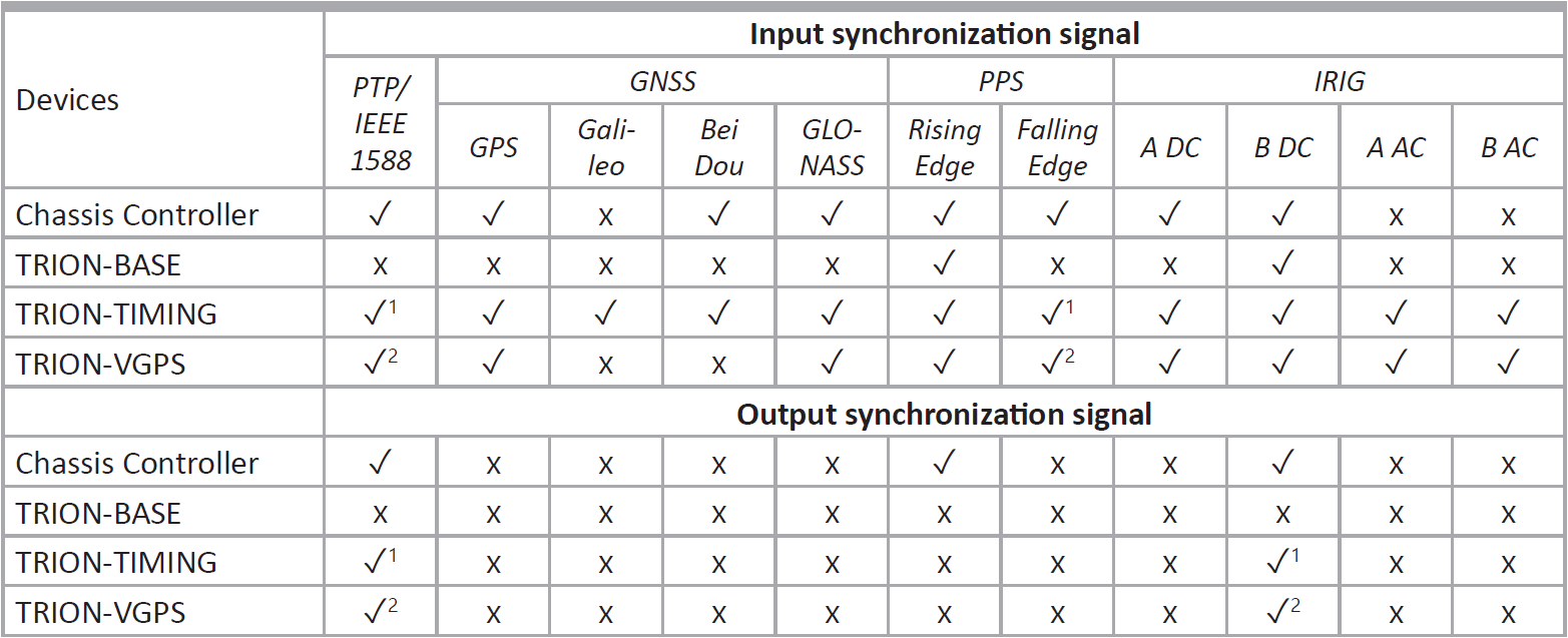
Fig. 125 Compatibility of TRION modules and synchronization source
TRION-TIMING-V3 required; 2) TRION-VGPS-V3 required
Synchronization with a TRION-BASE board
If a TRION-BASE board is mounted to the first system slot (Star slot), the system can be synchronized with an external IRIG-B-DC or a PPS signal (synchronization to the Rising signal edge).
To use either IRIG-B-DC or the PPS signal as synchronization signal, connect the signal to the IRIG input of the TRION-BASE board (PPS signal must be input as well via the IRIG connector). Uncheck the Auto setup box in the Sync Setup and select either IRIG or PPS in the Synchronization Input menu (see Fig. 126).
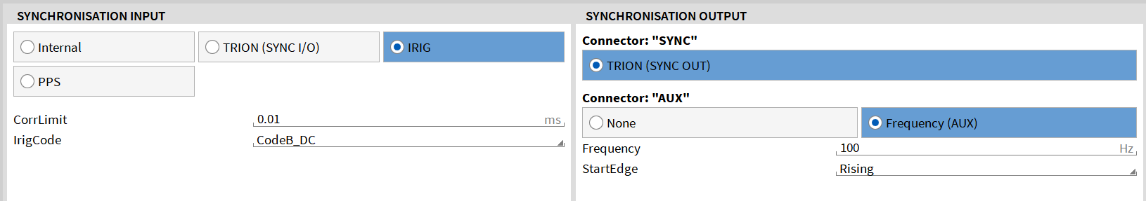
Fig. 126 Selecting an external synchronization source using a TRION-BASE board
The Sync indicator in the upper right corner of the menu will be
Red, if no valid synchronization signal is connected to the SYNC I/O connector
Orange, if a valid synchronization signal is connected to the SYNC I/O connector but the system is not locked yet (this might take some seconds and will be locked automatically)
Green, if a valid synchronization signal is connected to the SYNC I/O connector and the system is locked.
The Sync indicator is available in the Action bar as well if the Sync Setup is closed (see ② in Fig. 14).
Note
If an external synchronization signal is applied to the system, the signal can be forwarded via the TRION-SYNC-BUS (see TRION-SYNC-BUS) as well to synchronize other DEWE3 chassis.
In addition, the TRION-BASE board offers an AUX connector which can output a rectangular (LVTTL) signal to synchronize other devices, i.e. a GigE camera, to the TRION hardware clock. To do so, enable the Frequency (AUX) switch in the Synchronization Output setup (see Fig. 126). The Frequency can be set from 10 Hz to 10 MHz and the Start Edge can be the Rising or Falling signal edge.
Synchronization with a TRION-TIMING/VGPS board
When a TRION-TIMING or TRION-VGPS board is mounted to the first system slot (Star slot), in addition to TRION (SYNC I/O), multiple other synchronization options are available:
IRIG (A-DC, A-AC, B-DC, B-AC)
PPS (rising edge; falling edge requires TRION-TIMING/VGPS-V3)
GNSS (VGPS supports GPS & GLONASS; TIMING supports GPS, GLONASS, BeiDou, Galileo)
PTP (requires TRION-TIMING/VGPS-V3)
LVTTL
I. IRIG
To use an IRIG signal as synchronization signal, connect the signal to the IRIG input of the TRION board. Uncheck the Auto setup box in the Sync Setup and select IRIG in the Synchronization Input menu. Go to the IrigCode drop-down menu and select the correct IRIG Code (see Fig. 127).
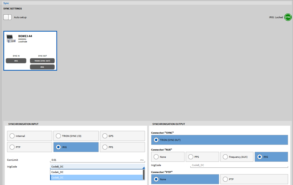
Fig. 127 Sync settings for IRIG input synchronization
The TRION-TIMING/VGPS-V3 board also supports the output of an IRIG B-DC signal. This can be configured in section Synchronisation Output -> Connector: “IRIG/BNC” -> IRIG (see Fig. 128).
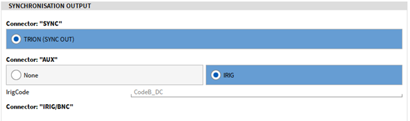
Fig. 128 Sync settings for IRIG output synchronization
Note
The IRIG/BNC connector on TRION-TIMING/VGPS-V3 boards can be used for IRIG input or output, but not simultaneously. Hence, dual IRIG input and output is not supported.
II. PPS
To use a PPS signal as synchronization signal, connect the signal to the IRIG connector of the TRION board (PPS signal must be input as well via the IRIG connector). Uncheck the Auto setup box in the Sync Setup and select PPS in the Synchronization Input menu (see Fig. 129). If the system shall be synchronized to the Rising signal edge, go to the InvertedInput drop-down menu and select False. If the system shall be synchronized to the Falling signal edge, go to the InvertedInput drop-down menu and select True.
Note
Only TRION-TIMING/VGPS-V3 boards support PPS synchronization to the falling signal edge.
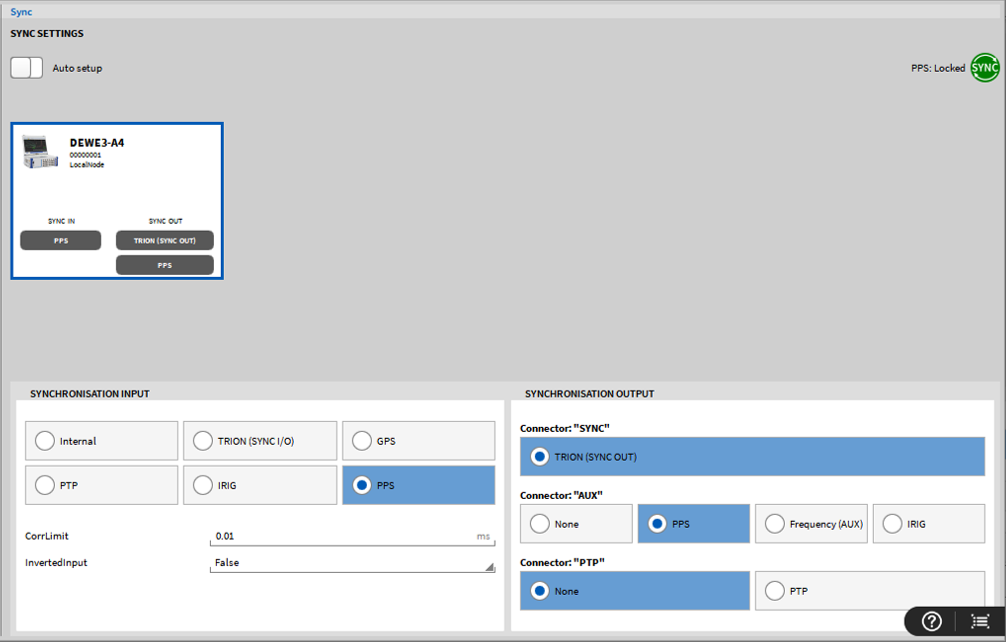
Fig. 129 Sync settings for PPS synchronization
III. GPS
To use GPS as synchronization signal, connect the antenna to the GPS input of the TRION board. Uncheck the Auto setup box in the Sync Setup and select GPS in the Synchronization Input menu (see Fig. 130).
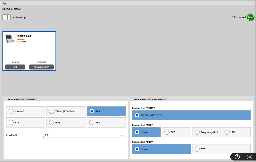
Fig. 130 Sync settings for GPS synchronization
Note
In this context, the term GPS refers to all GNSS sources. The source ultimately used depends on the available signal and the antenna.
IV. PTP/IEEE 1588
To use a PTP signal as synchronization signal, connect the signal to the PTP input of the TRION board. Uncheck the Auto setup box in the Sync Setup and select PTP in the Synchronization Input menu (see Fig. 131).
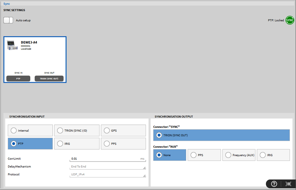
Fig. 131 Sync settings for PTP input synchronization
gPTP is a specialized constrained profile of PTP, not a separate protocol; gPTP runs directly over Ethernet frames (Ethernet layer 2) with strict rules for precision and determinism. The PTP parameters shown can be edited in Expert mode.
Note
If an external synchronization signal is applied to the system, the signal can be forwarded via the TRION-SYNC-BUS (see TRION-SYNC-BUS) as well to synchronize other DEWE3 chassis. If a NEX[DAQ] is used as a PTP master, the date/time from the connected PC is used.
TRION-TIMING/VGPS-V3 additionally supports PTP out. Thus, a DEWETRON measurement device can also be used as a PTP master to synchronize other devices via PTP. To do so, on the PTP Master use the PTP connector as the output source and connect it to an additional input port. Uncheck the Auto setup box in the Sync Setup and select PTP in the Synchronization Output menu (see Fig. 132).
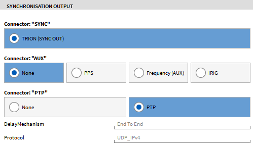
Fig. 132 Sync settings for a PTP input synchronization
PTP input and output use the same connector on TRION-TIMING/VGPS-V3 boards. Hence, simultaneous use of PTP input and output is not possible.
V. LVTTL output
In addition, the AUX connector of the TRION-TIMING/VGPS modules can output a rectangular (LVTTL) signal to synchronize other devices, i.e., a GigE camera, to the TRION hardware clock. To do so, enable the Frequency (AUX) in the Synchronization Output setup (see Fig. 127). The Frequency can be set from 10 Hz to 10 MHz and the Start Edge can be the Rising or Falling signal edge. For the AUX output to fully work, the “Use Chassis Controller for Sync” option must be set to false.
Synchronization with a Chassis Controller of any DEWE3 system
The chassis controller of any DEWE3 system supports a range of external synchronization options, similar to the TRION-TIMING/VGPS modules. These include IRIG, PPS, LVTTL, PTP, and GPS signals.
For IRIG and PPS synchronization, the connection must be made through the digital I/O connector. Use pin 8 for input signals and pin 24 for output signals (see Fig. 133 for the entire connector pinout). Because input and output are assigned to separate pins, the chassis controller is capable of handling simultaneous IRIG input and output. In addition to IRIG/PPS output, pin 24 can also be configured to emit a rectangular LVTTL signal. This is useful for synchronizing external devices such as GigE cameras. The output frequency of the LVTTL signal is configurable and can range from 1 Hz to 10 MHz.
Note
To use IRIG and PPS at the chassis controller, the hardware option DEWE3-OPT-IRIG/PTP is required.
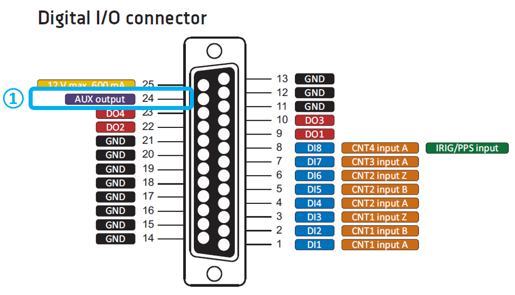
Fig. 133 DIO pinout of chassis controller
To synchronize the system using GPS, simply connect the GPS antenna to the corresponding GPS input on the chassis controller. Uncheck the Auto setup box in the Sync Setup and select GPS in the Synchronization Input section.
Note
To use the GPS input at the chassis controller, the hardware option DEWE3-OPT-GPS is required.
PTP synchronization is also supported and uses a dedicated connector on the chassis (see Fig. 134). Since this connector is used for both input and output, the chassis controller can function as either a PTP slave or a PTP master.
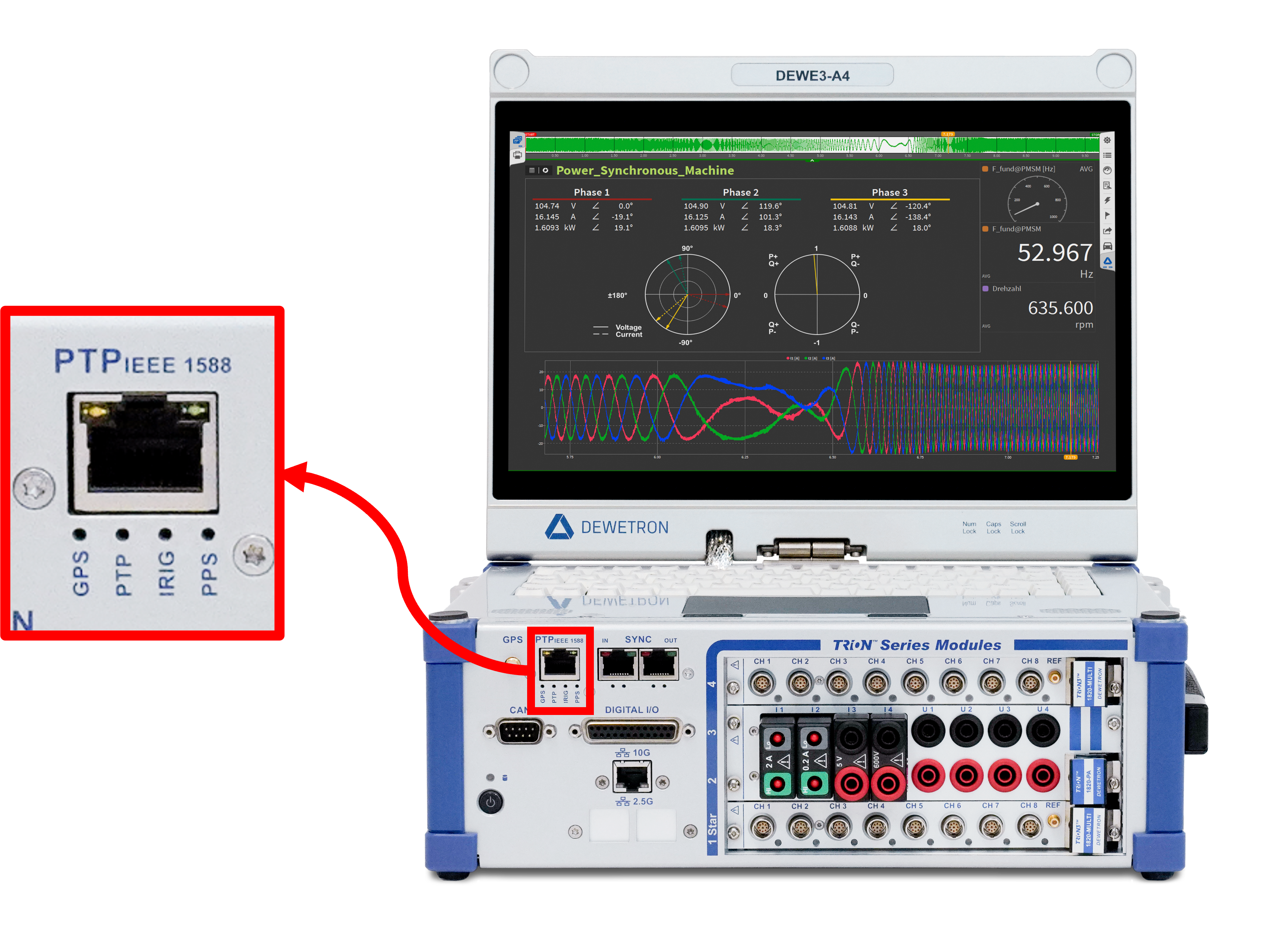
Fig. 134 PTP connector on chassis
Note
To use the PTP input at the chassis controller, it requires the hardware option DEWE3-OPT-IRIG/PTP. In addition to use the PTP Master option requires the software license OXY-OPT-PTP-OUT in combination with the firmware version >R6.6.1. Further note that this option is not available in EVALUATION mode.
The process for configuring these synchronization signals follows the same general steps as described for TRION-TIMING/VGPS modules. For detailed setup instructions, refer to the corresponding sections.
General remarks on PPS, IRIG and PTP synchronization
PPS is the abbreviation for Pulse Per Second. PPS signals provide one pulse per second whose Rising or Falling Edge is used for data synchronization.
PPS signals are usually provided by GPS receivers or IMUs, i.e. GeneSys ADMA’s or OxTS RT’s
PPS signals may look like the following:
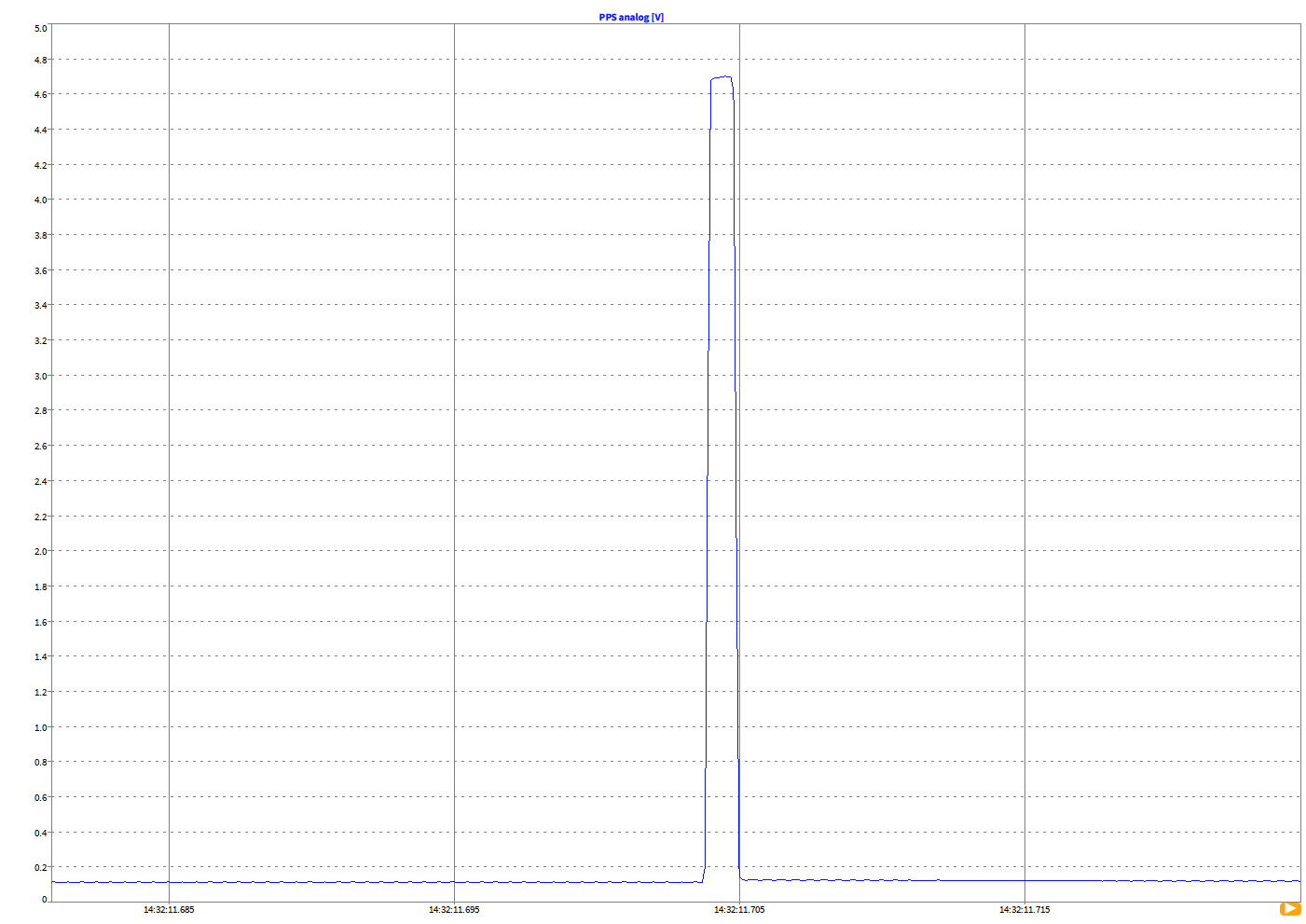
Fig. 135 PPS signal - example 1
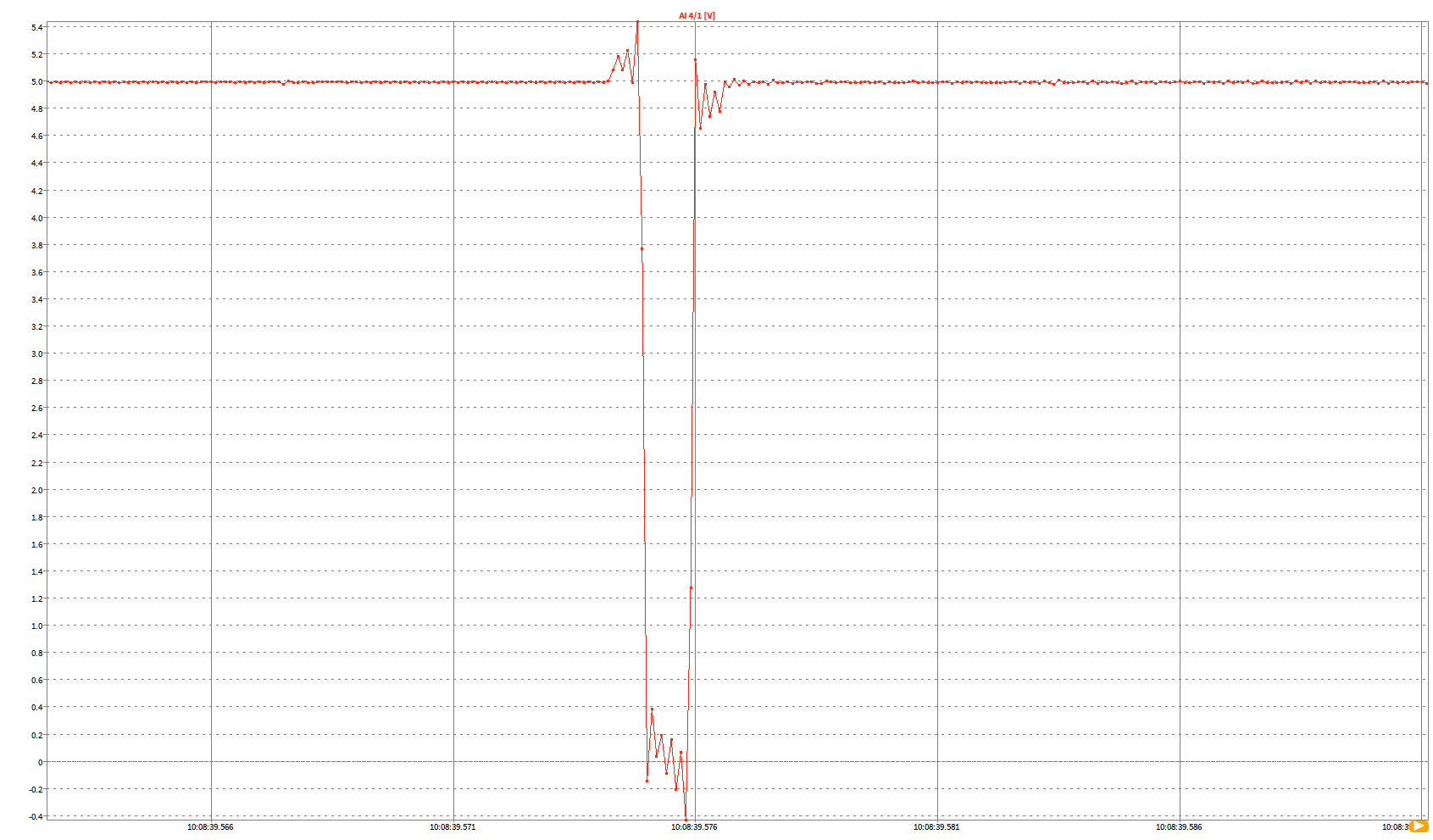
Fig. 136 PPS signal - example 2
The IRIG timecode is used to control a PLL, which is then used as the system time base.
The IRIG connector also has an indication LED flashing either green or red

Fig. 137 IRIG connector; detailed view
The IRIG LED has the following indication:
OFF |
ON |
Description |
|
|---|---|---|---|
GREEN (flashing) |
20 % |
80 % |
SYNC IN not available |
RED (flashing) |
80 % |
20 % |
SYNC detected, not locked |
Green (flashing) |
80 % |
20 % |
SYNC detected and locked |
PTP is the abbreviation for Precise Time Protocol and is a protocol for clock synchronization throughout a computer network.
PTP is defined in the IEEE 1588 standard.
Servers
MODBUS Server
OXYGEN offers an integrated MODBUS server plugin that allows to transmit measurement data to an external MODBUS client.
For more information, refer to the to the OXYGEN MODBUS Technical Reference Manual which is available on the DEWETRON CCC-portal (https://ccc.dewetron.com/).
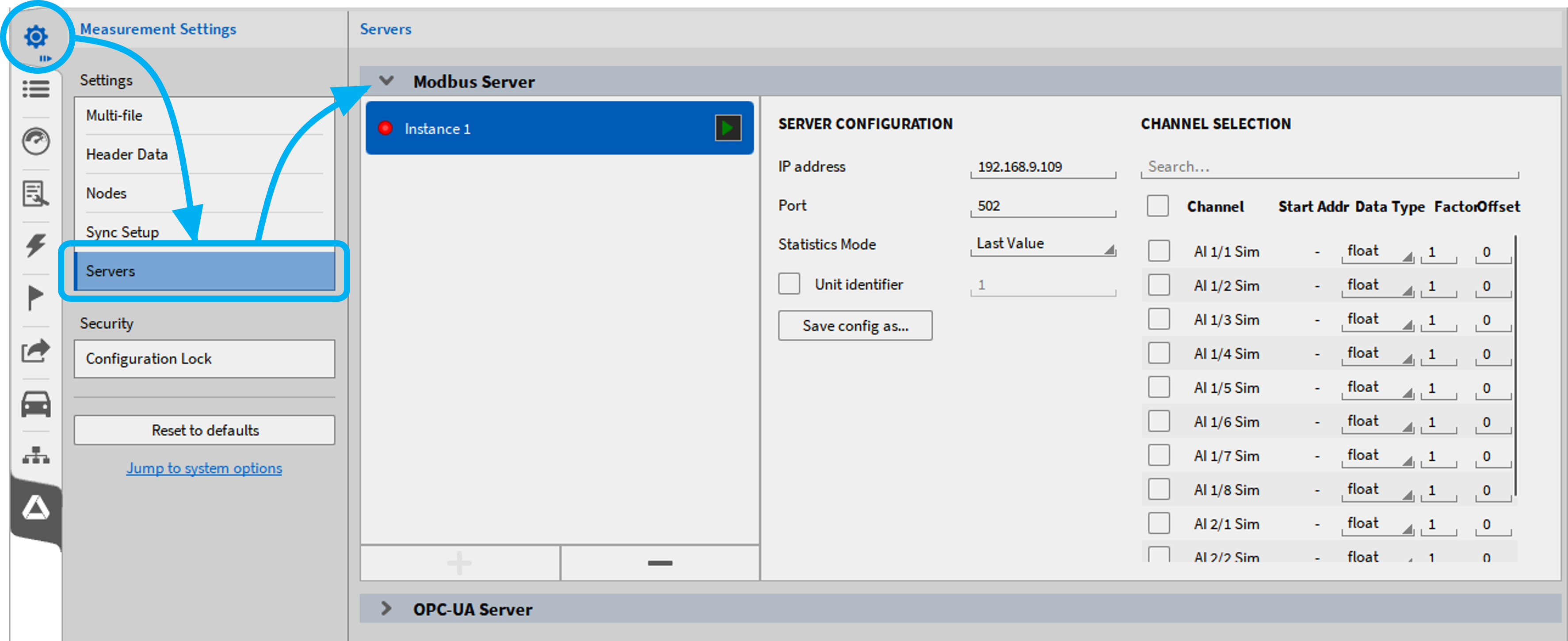
Fig. 138 MODBUS Server
OPC UA Server
OXYGEN offers an integrated OPC UA Server plugin that allows data to be published to external OPC UA clients.
For more information, refer to the to the OXYGEN OPC UA Technical Reference Manual which is available on the DEWETRON CCC-portal (https://ccc.dewetron.com/).
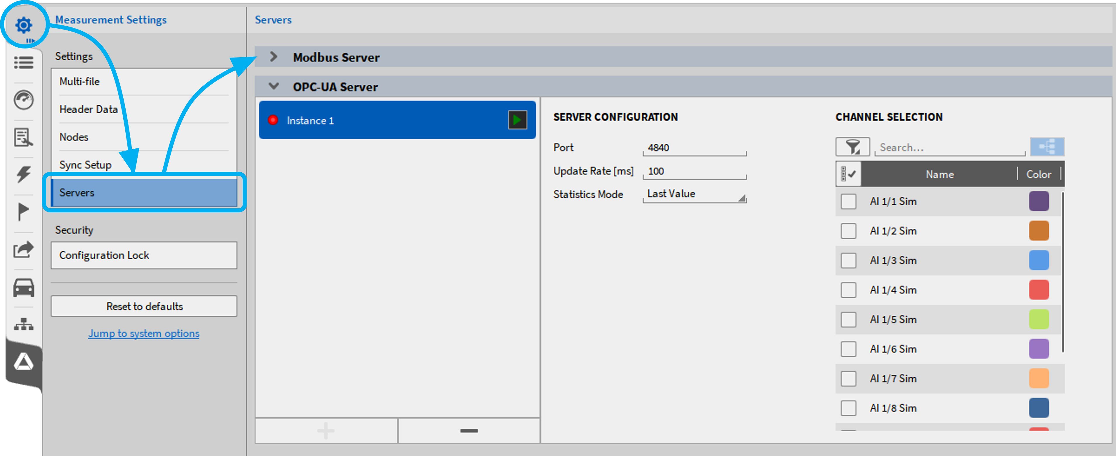
Fig. 139 OPC UA Server
Security
Configuration lock
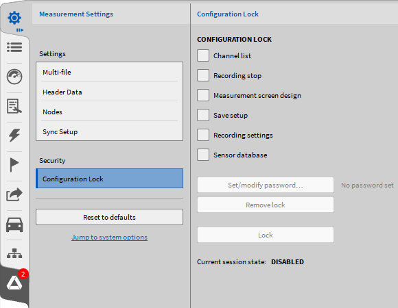
Fig. 140 Security settings
In the Security menu, the user can log certain measurement setup and recording options against unauthorized or unwanted changes and protect the measurement setup. These settings are stored to the measurement setup.
If this option is enabled, the settings are automatically locked after loading the setup.
The following functionalities can be locked:
Channel List: Protects all settings in the Channel List (see Data channels menu). If this option is enabled, the Channel List settings can only be viewed. To edit the settings, the setup must be unlocked by entering the correct password. The password must be entered in the Security tab of the Measurement settings. Additionally, no acquisition restart will be made when switching between measurement screen and channel list.
Recording Stop: A password has to be entered to stop or pause a recording based on a measurement setup that has this option enabled. A popup will open to enter the password after pressing the stop or pause button.
Measurement Screen design: If this option is enabled, a password has to be entered to access the Design Mode (see Adding an instrument to the measurement screen and channel assignment), to change the instrument’s channel assignment, axes scaling or their instrument properties. The password must be entered in the Security tab of the Measurement settings.
Save Setup: If this option is enabled, a password has to be entered to save changes on the measurement setup. A popup will open to enter the password after pressing the save setup button.
Recording Settings: If this option is enabled, a password has to be entered to edit the Data Storing and Multi-File settings (in Measurement settings see General settings) and the settings in the Triggered Events menu (see Triggered Events). The password must be entered in the Security tab of the Measurement settings. Additionally, no acquisition restart will be made when switching between measurement screen and channel list.
Sensor database: If this option is activated, a password must be set as before. This means that the sensor database can no longer be edited unless the lock has been removed in the security menu.
To activate the lock of certain setup settings, proceed the following steps:
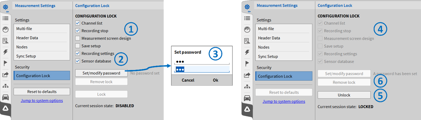
Fig. 141 Activation setup lock
Select the settings that shall be locked (see ① in Fig. 141).
Press Set/modify password (see ② in Fig. 141).
Enter the password and confirm it (see ③ in Fig. 141).
The selected settings will be locked afterwards (see ④ in Fig. 141).
To unlock the settings again, press the Unlock button and enter the password (see ⑤ in Fig. 141).
To remove the lock from the setup again, press Remove lock in the unlocked state (see ⑥ in Fig. 141).