OXYGEN provides two different recording modes: The Waveform Recording and the Statistics Recording.
The Waveform Recording stores all channels that are enabled for recording @full sample rate into the data file.
The Statistics Recording stores only the statistical values MIN, MAX, AVG and RMS of an adjustable time window between 0.1 and 10 seconds into the data file. The Statistics Recording is also only done for the input channels that are enabled for recording.
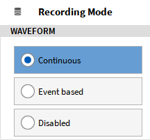
Both recording modes can be enabled independently. The default software setting enables both Continuous Waveform Recording and Statistics Recording (Statistics window: 1 second).
If the user does not want OXYGEN to enable Waveform Recording for the complete recording time but only when certain input signal levels are reached, he can control that with the Event Based Waveform Recording (=Triggering) which is explained in the following sections.
Event Based Waveform Recording and Statistics Recording
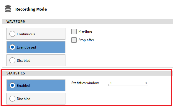
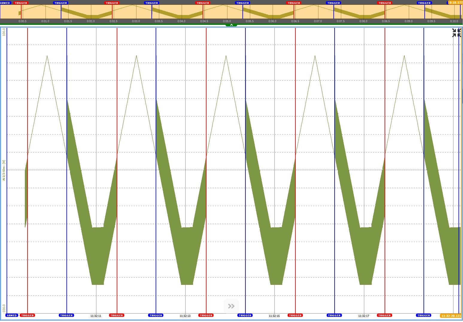
A very useful combination is the Event Based Waveform Recording in combination with the Statistics Recording. Especially over long measurement periods with rare trigger events, the Statistics Recording gives the user the guarantee that data was recorded without consuming much hard disk space. In the data file, the waveform data is plotted when the trigger event was active and otherwise the MIN and MAX value of the Statistics Recording data (see Fig. 529).
Fig. 529 Event Based Waveform Recording (marked in red) and enabled Statistics Recording
Automatic Measurement Start
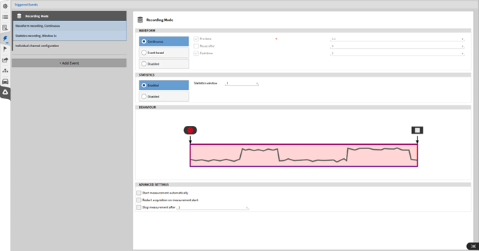
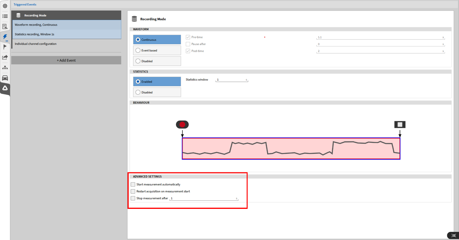
OXYGEN offers the possibility to start the measurement automatically after the software has started. To activate the Automatic measurement start, enlarge the Triggered Events menu to the full screen and check Start measurement automatically in the Advanced Settings (see Fig. 530).
In case of Continuous Waveform Recording (refer to Triggered Events), the measurement will start automatically after OXYGEN has started and makes the manual press of the Recording button obsolete (see ⑧ in Fig. 14).
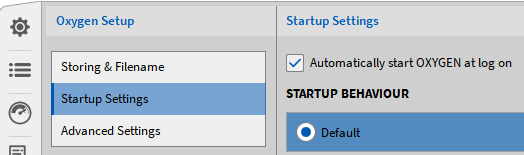
As DEWETRON measurement systems start automatically after they are connected to a power supply, the measurement can start automatically after the measurement system is powered without any interaction of the user. To start OXYGEN automatically, the startup setting “Automatically start OXYGEN at log on” can be enabled.
The Restart acquisition on measurment start checkbox enables calculated channels and CNT channels to be reset when recording is started.
In case of Event based Waveform Recording (refer to Triggered Events and Record action), the measurement will start automatically when the Start Recording condition (see Record action) is active. Therefore, it is not necessary to arm the trigger manually anymore (see Arming the Trigger).
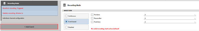
If the Event Based Recording is activated, the user must add one or several Trigger Events that regulate the recording start. This can be done via the +Add Event button (see Fig. 532). Optionally the user can also store the data before the trigger event was reached by adding a Pre-time between 0 and 500 seconds and he can also define a time after which the record is paused automatically (Pause after). To increase the pre-time, increase the capacity of the freeze buffer, see Advanced settings.
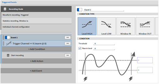
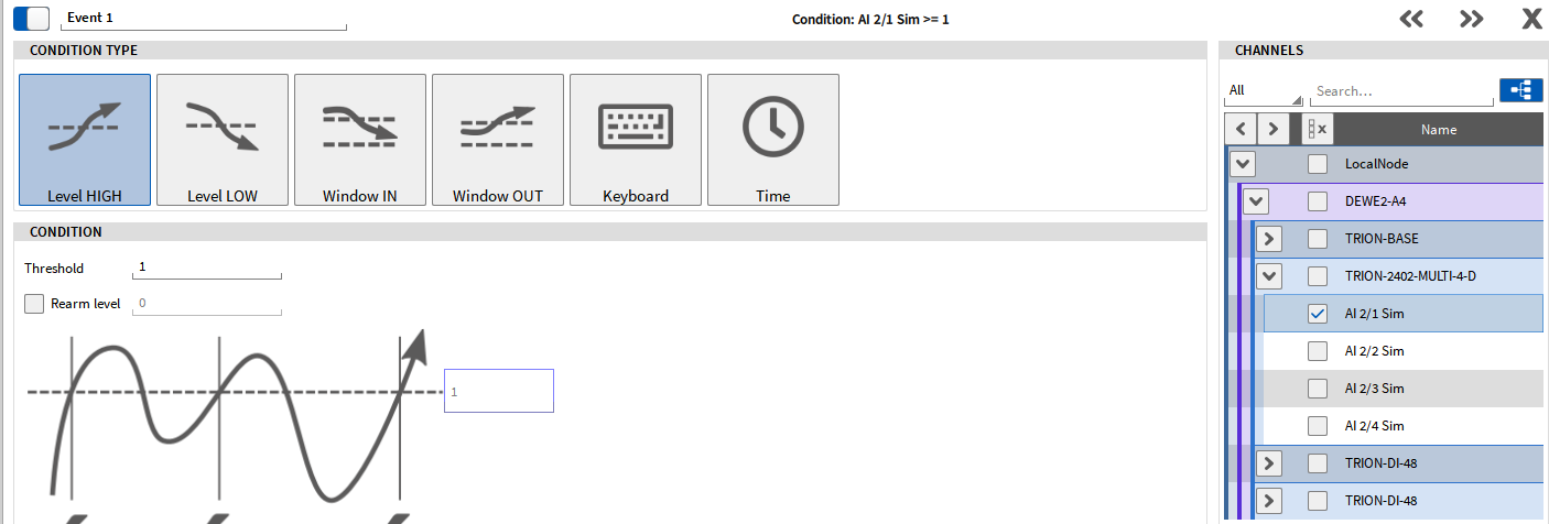
After an event was added, the user must define an event condition and assign a data channel that is surveilled by the event condition:
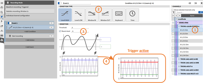
Fig. 533 Define an Event Condition and Trigger on Level HIGH
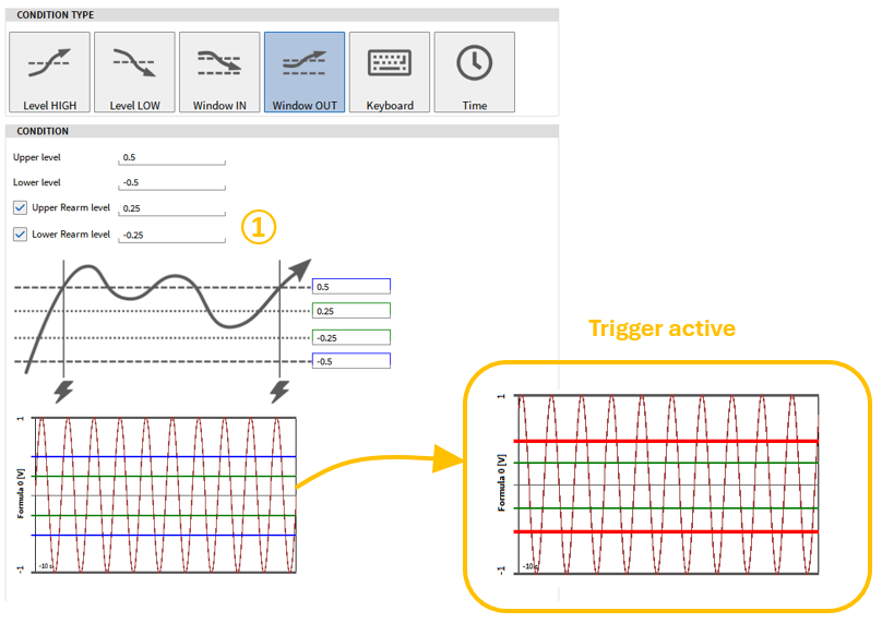
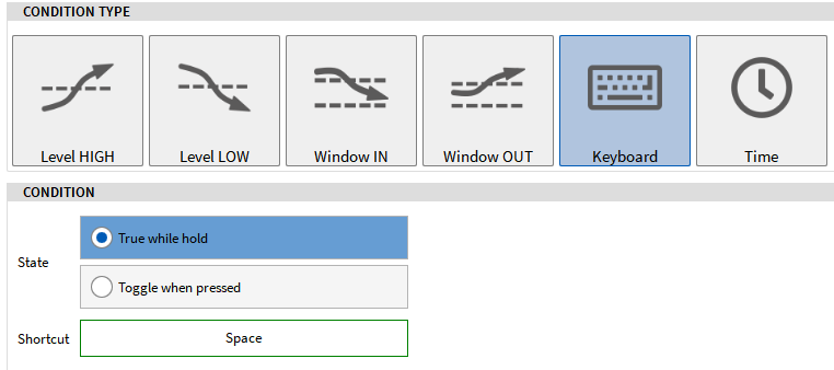
The channel to be triggered on can be selected from the channel list on the right screen side (see ① in Fig. 533). After selecting the channel, a preview window is displayed (see ④ in Fig. 533). The measuring range displayed in the preview window is the set measuring range of the channel to be triggered. The preview window also contains the set threshold and rearm level. As soon as the threshold value is exceeded and the trigger is active, the line for the threshold value in the preview window changes color from blue to red. The user can select between six different event conditions (see ② in Fig. 533):
Level HIGH: Activate Event if selected signal exceeds defined Threshold. A Rearm Level that must be passed before the trigger is activated again can optionally be defined (see ③ in Fig. 533).
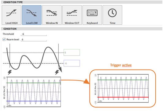
Level LOW: Activate Event if selected signal falls below defined Threshold. A Rearm Level that must be passed before the trigger is activated again can optionally be defined (see Fig. 534).
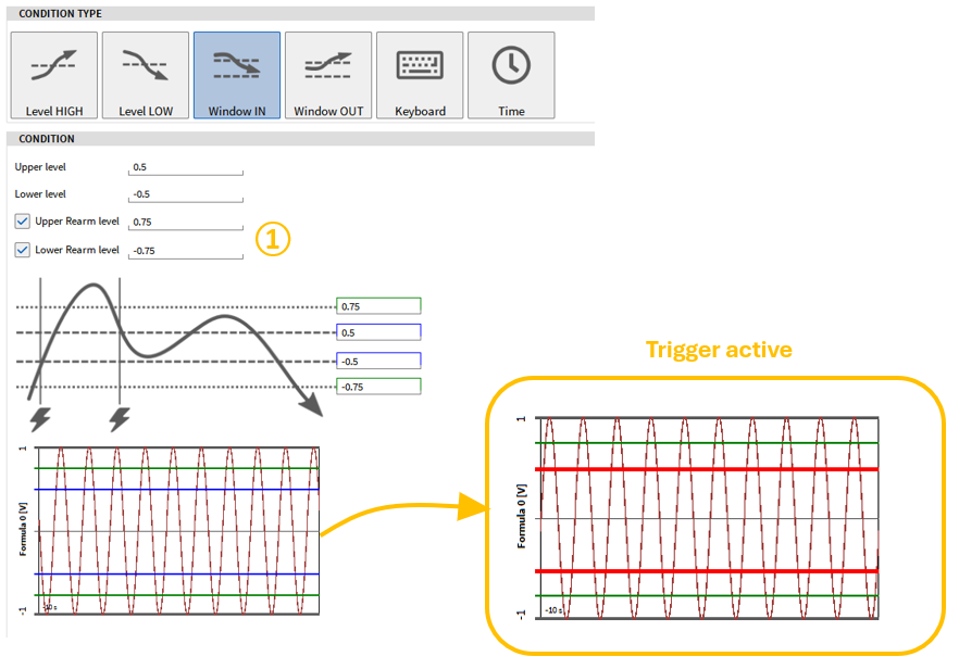
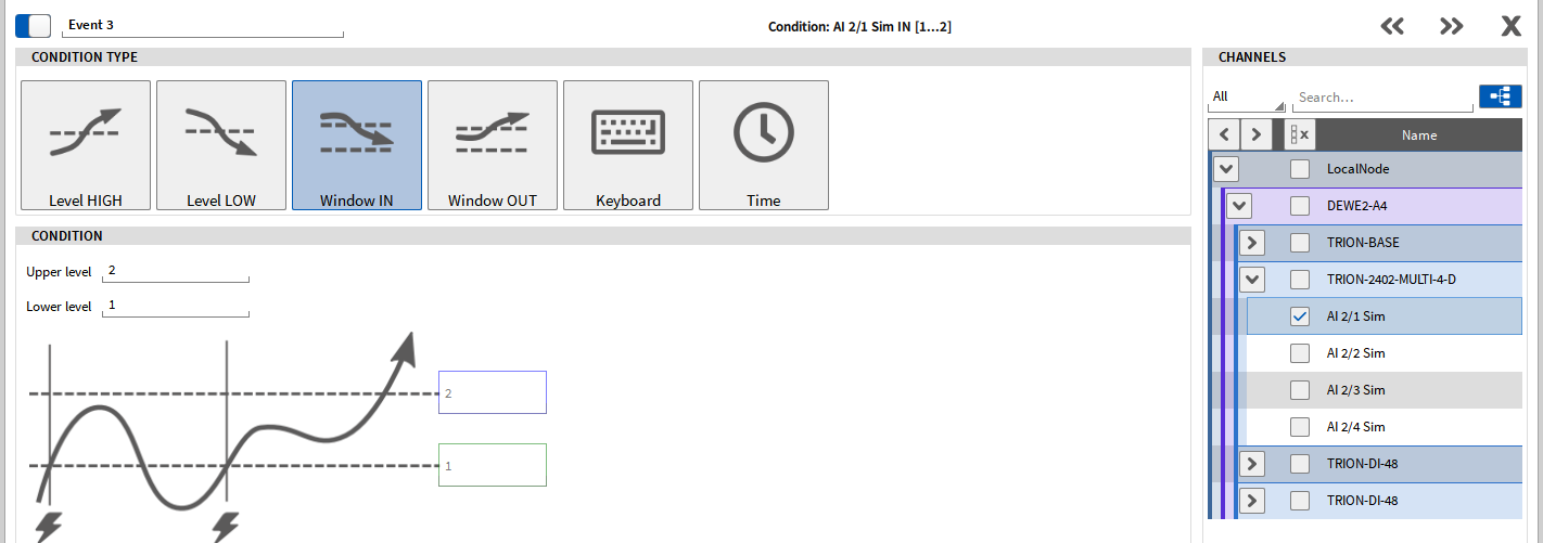
Window IN: Activate Event if selected signal is within a certain range. The user can define an upper and a lower limit (see Fig. 535). A Rearm Level that must be passed before the trigger is activated again can optionally be defined for the lower and upper limit (see ① in Fig. 535).
Window OUT: Activate Event if selected signal is out of a certain range. The user can define an upper and a lower limit (see Fig. 536). A Rearm Level that must be passed before the trigger is activated again can optionally be defined for the lower and upper limit (see ① in Fig. 536).
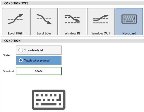
Keyboard Event: Control Trigger via the keyboard. The user can select two different states: True while hold activates the Event if the selected key is pressed and Toggle when pressed toggles between activating and deactivating the Event every time the button is pressed. The key can be selected with a click on the field right to Shortcut. In this example, the Space key was selected.
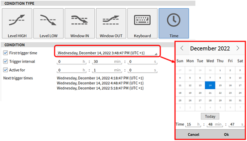
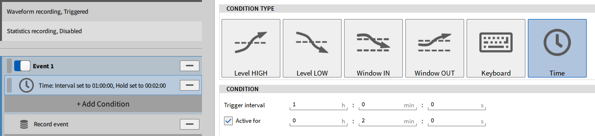
Time Event: The event is activated in the dependency of a time condition. In the example in Fig. 538, the event is activated every 30 minutes for a duration of 1 minute, starting at 15:48:47 on Wednesday 14th of December 2022. If the Active for option is not enabled, the Event will be active for one Sample interval, i.e. for 1 ms if the sample Rate is 1 kHz. The red indicator (see ① in Fig. 539) won’t highlight if the Active for option is not enabled.
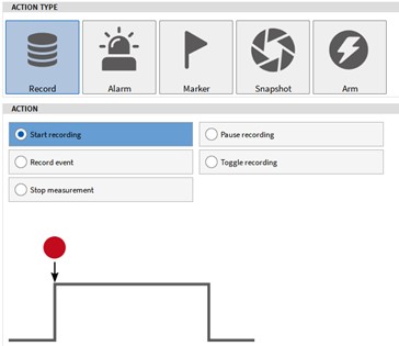
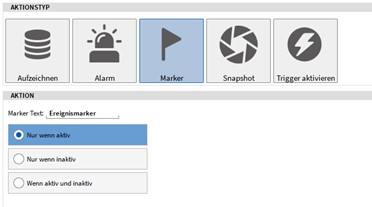
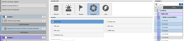
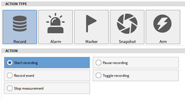
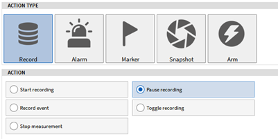
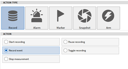
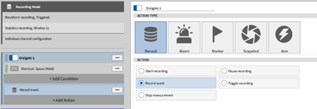
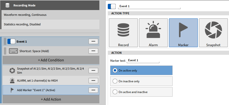
After the Event Condition is configured the user must define an action that shall be performed when the event is activated, the Event Action. Four different actions are available: A Record action, an Alarm action, a Marker action and a Snapshot action. Each action has a submenu with different possibilities that are explained in the following sections.
Note
It is possible to add several Event Actions to the same Event
Start Recording: Starts the recording mode when the event is activated
Pause Recording: Pauses the recording mode when the event is activated
Record Event: Recording is enabled if the event is active
Toggle Recording: Toggles recording status if the event is activated
Stop measurement: Stops the recording mode when the event is activated
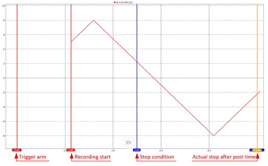
Post-time: a post-time can be defined in the trigger menu overview (see Fig. 528 or Fig. 532). If activated, the recording stops after the defined time when the stop measurement event is activated. For example, if a post-time of 5 seconds is defined, the recording stops 5 seconds after the actual condition with the stop measurement action was defined (see Fig. 541).
Fig. 541 Trigger – example of stop measurement action with post time
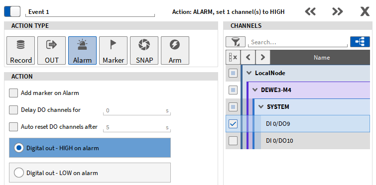
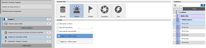
Add marker on Alarm: A marker will be set when the event is activated
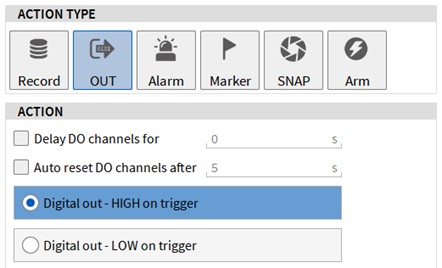
Define delay for digital output: The digital output is only set to LOW or HIGH after the defined delay.
Define delay for automatic reset of digital output: The digital output is only reset after the defined delay.
Digital out – HIGH on alarm: The status of a digital out channel will be set to High when the Event is activated. The channel(s) can be selected from the channel list on the right-hand side. An automatic reset of the channel after 0 - 3600 seconds can optionally be selected.
Digital out – LOW on alarm: The status of a digital out channel will be set to Low when the Event is activated. The channel(s) can be selected from the channel list on the right-hand side. An automatic reset of the channel after 0 - 3600 seconds can optionally be selected.
Note
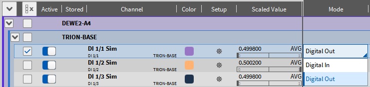
To use connected digital channels as Digital Out channels the Channel Mode must be set to Digital Out in the Data Channels menu (see Fig. 544).
Fig. 544 Changing the channel mode of a digital channel
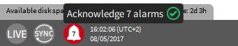
The number of alarms is counted and displayed in the Action bar. To quit the alarms, click on the bell symbol in the action bar and click on the green check mark (see Fig. 545).
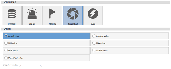
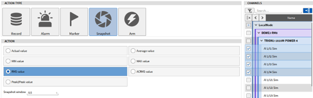
The Snapshot action can be used to query the Actual Value, Average, MIN, MAX, RMS, ACRMS or Peak2Peak value of one or several channels that may be selected on the right-hand side of the menu (see ① in Fig. 533) and copy this value to a new channel. This channel is added to the Channel List and can be found in the Snapshot: Event x section (see Fig. 548). If a statistical value is selected, the calculation time interval can be defined in the Snapshot window input field (see Fig. 547). The time interval is applied prior to the activation of the event.
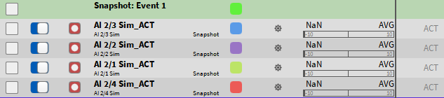
The same snapshot action can be applied to several channels by selecting them in the Channel list on the right-hand side (see Fig. 549). An own snapshot channel for each selected channel is created in the Channel List (see Fig. 550). Selecting several channels in the Snapshot Action menu will result in an own snapshot channel in the Channel List for each selected channel
Fig. 549 Selecting several channels in the Snapshot Action menu
Fig. 550 Snapshot channel in the Channel List for each selected channel
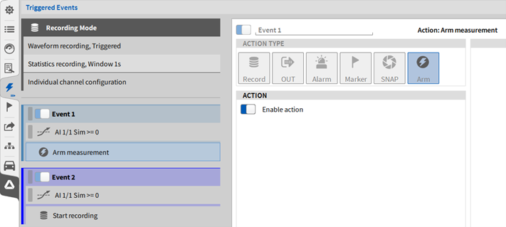
The Activate trigger action can be used to automatically arm and thus activate other set trigger actions. After the trigger condition has been met, eventbased recording is enabled and recording starts and pauses according to the defined trigger events. Measurement data is stored in ONE file. This action can also be performed manually (see Fig. 551).
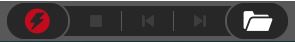
If Event Based Waveform Recording is selected, a flash will appear within the sign of the record button (see Fig. 552).
Fig. 552 Action bar with enabled Event Based Waveform Recording
After pressing the record button, the Event Based Waveform Recording is armed and the recording will be started and paused according to the defined trigger events. Measurement data will be written to ONE data file.
Note
If the trigger condition is active while arming the trigger, the trigger will not be detected as the trigger condition is not passed.
Challenge: Start Recording when the value of a certain analog input channel exceeds 1 and Pause Recording again when the value exceeds 2.
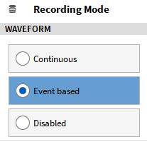
Select Event based Waveform Recording as Recording Mode (see Fig. 553):
Fig. 553 Event based Waveform Recording selection
Add an Event. Select Level High as Condition Type and set the Threshold to 1. Select the analog input channel to be triggered on in the Channel List on the right-hand side (see Fig. 554):
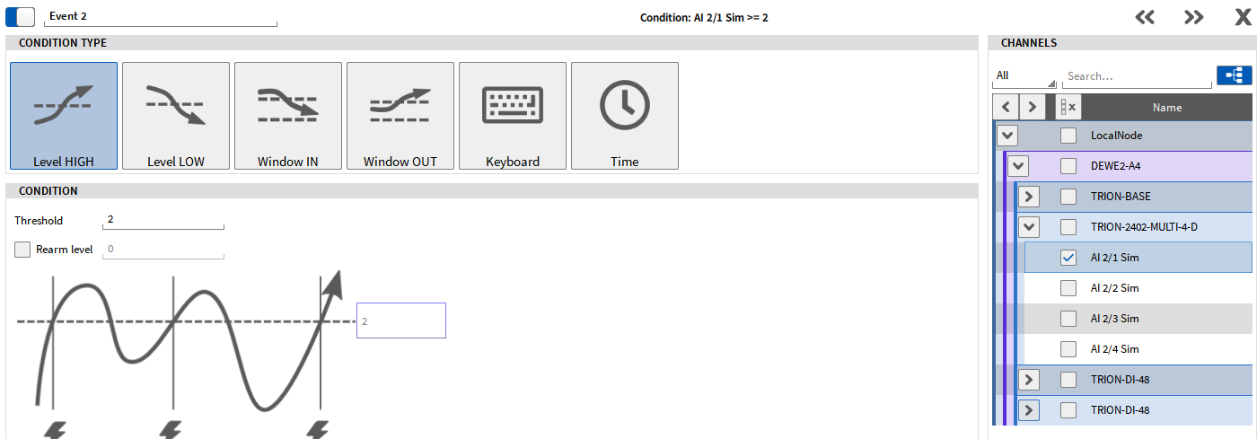
Add another event. Select Level High as Condition Type and set the Threshold to 2. Select the analog input channel to be triggered on in the Channel List on the right-hand side (see Fig. 556):
Challenge: Record data every time the value of an analog input channel is within 1 and 2. The difference to the example above in Example 1 is that in Example 1 data recording is not started when the value decreases below 2 and does not pause the recording when the value decreases below 1. In this Example 2, it is the case as well.
Select Event based Waveform Recording as Recording Mode (see Fig. 558):
Fig. 558 Event based Waveform Recording selection
Select Window IN as Condition Type and set the Lower level to 1 and the Upper level to 2. Select the analog input channel to be triggered on in the Channel List on the right-hand side (see Fig. 559):
Challenge: When the space key is pressed, the RMS value 0.5s prior to the event of 4 analog input channels shall be queried using the snapshot action. When the space button is pressed, a marker shall be added to the time position and a Digital Out channel shall be set to High state.
Select Continuous Waveform Recording as Recording Mode (see Fig. 552):
Select Snapshot as Action Type and select RMS value as Action with a Snapshot window of 0.5s. The analog input channels used for the data query can be selected in the channel list on the right-hand side (see Fig. 567). Data will be queried in the moment the Event configured above is activated.
To set the Digital Channel to High state, add another Action by pressing the +Add Action button, select AlarmAction Type and select Digital out – High on alarm as Action. The Digital out channel to be set can be selected in the channel list on the right-hand side (see Fig. 566). The channel mode of the desired Digital channel must be set to Digital out in the Channel List (see Fig. 544).
To add a Marker in the data file at the instant of time the Event is activated and data is queried, add another Action by pressing the +Add Action button, select Marker Action Type and select On active only as Action. A marker is now added when the Event is activated.
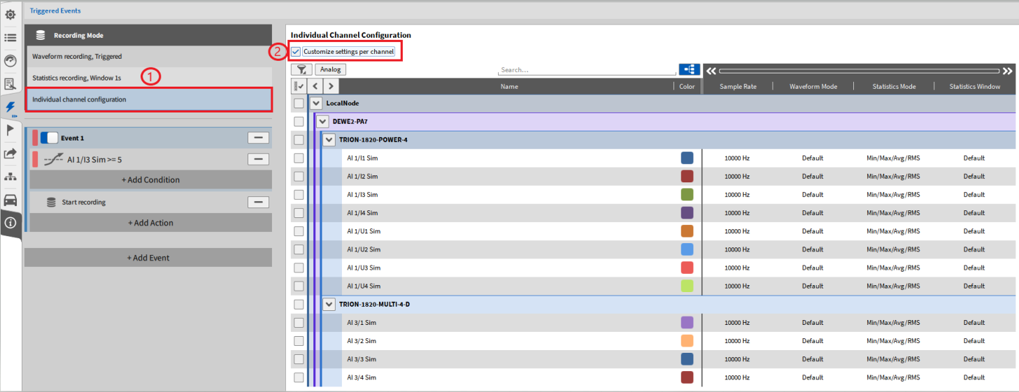
The advanced storing modes are available in the Trigger Menu, in the individual channel configuration section (see ① in Fig. 569). The individual channel configuration includes the following options:
Store channels at different sample rates on triggered events
Choose between different options for the statistics data
Set different time windows for the statistics data for individual channels
In order to activate the individual channel configuration click on the checkbox button Customize settings per channel (see ② in Fig. 569).
Fig. 569 Individual channel configuration in Trigger Menu
In this channel configuration some known settings from the Data Channel List can be found, like the channel filter or color bar. These settings are described in Data channels menu. To keep the overview the three relevant columns for the individual channel configuration will be explained here:
Waveform Mode
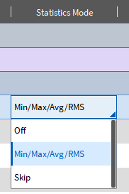
Statistics Mode
Statistics Window
Note
The sample rate is shown here, just like in the data channel list, but it cannot be changed in this configuration menu. In order to change the sample rate for individual channels, go to the Data Channel list and refer to Channel-wise Sample Rate Selector, where it is described in detail how to change sample rates channel-wise.
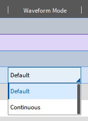
The Waveform Mode offers two different options seen in Fig. 570.
Fig. 570 Options for Waveform Mode in Advanced Storing Modes
Default refers to the settings, which were made in the trigger menu. For details about the settings in the trigger menu, refer to Triggered Events. Continuous means, that the channel will always be stored, from the moment the trigger will be armed, and the trigger settings will be ignored. In this case this button in the action bar acts as the normal Recording start button.
Only after the event happens, the other channels with the default setting will also be stored with the defined sample rate. An exemplary representation on when and what channels are stored is shown in Fig. 571. Whenever the trigger is armed on the measurement screen in the action bar, the channels with the Waveform Mode Continuous are stored from that moment on. At the time the set events happen, also the channels with the Waveform Mode Default are stored at the defined sample rate.
Fig. 571 Representation of Continuous and Default Storing Mode
The selected sample rate at which the channel will be stored can be seen in the Sample Rate column. To change the sample rate, go to the Data Channel list.
Note
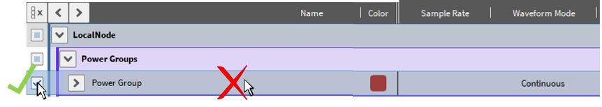
In case the Waveform Mode of a whole Power Group (all parameters within the Power Group) wants to be changed, the checkbox of the Power Group has to be specifically selected before changing the Waveform Mode (see Fig. 572). If only the row of the channel is clicked on, the Mode does not change for the individual Power channels. Of course, all the parameters of the Power Group can also set to an individual Waveform Mode.
Fig. 572 Changing Waveform Mode for a whole Power Group
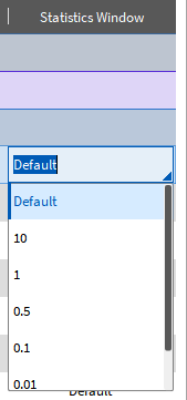
The time window to calculate the statistics data can be set individually per channel, seen in Fig. 574.
Default refers to the settings for the statistics data in the trigger menu, see Fig. 575.
For the time window a value from the drop-down list can be chosen or a value from up to 10 s can be entered.
Fig. 574 Options for Statistics Window in Advanced Storing Modes
Fig. 575 Settings for Statistical Data in Trigger Menu
Note
If the Statistics Data is disabled in the trigger settings (see Fig. 575), the columns Statistics Mode and Statistics Window disappear and are not shown in the Individual Channel Configuration anymore.
This section describes an example, to give a better understanding of the Advanced Storing Modes.
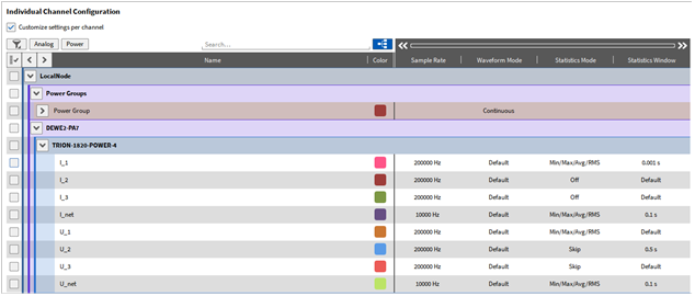
Fig. 576 and Fig. 577 both show the settings, which were made. This example shows how to continuously store the power parameters but only store the raw data in case of an event. For the raw data also different sample rates are set (refer to Channel-wise Sample Rate Selector) and different settings for the statistics data.
To continuously store the power parameters the Waveform Mode is set to Continuous (consider the note in Waveform Mode).
Whenever the trigger will be armed, all those parameters are recorded and stored.
The other channels of the TRION-1820-POWER-4 card are set to the Waveform ModeDefault. This means, that the trigger event settings are considered here. By looking at Fig. 576 it can be seen, that the recording will be started whenever the Trigger Channel rises above the defined threshold of 9 V. At this point the raw data channels are also recorded and stored with a sample rate of 200 kHz, or 10 kHz for channel I_net and U_net.
Additionally, those channels have different settings for the Statistics Data.
Channel I_1: The Min/Max/Avg/RMS value will be stored for a time window of 0.001 s.
Channel I_2 and I_3: Statistics Data is turned off and will not be calculated nor stored.
Channel I_net: The Min/Max/Avg/RMS value will be stored for a time window of 0.1 s.
Channel U_1: The Min/Max/Avg/RMS value will be stored for the default time window, which is set in the trigger settings and is per default of 1 s.
Channel U_2: only the first sample of the defined time window of 0.1 s is stored.
Channel U_3: only the first sample of the default time window of 1 s, which is set in the trigger settings, is stored.
Channel U_net: The Min/Max/Avg/RMS value will be stored for a time window of 0.1 s.
The individual channel configuration should be done carefully to make the right settings, since complex setups can be created like this.

 acts as the normal Recording start button.
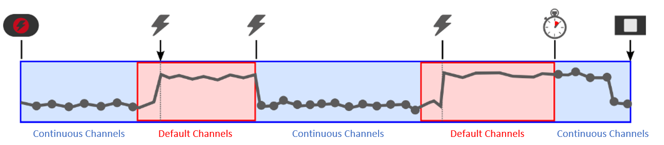
 up to 10 s can be entered.