Harmonic Analysis Reference (OPT-POWER-ADV)
This Chapter describes the measurement of
Harmonics (0 to 1000th Order)
Interharmonics (0.5 to 49.5th Order)
Higher Frequencies (2 to 9 kHz)
Supraharmonics (8 to 150 kHz)
The further mentioned calculation methods are complying with IEC 61000-4-7 for 50 Hz and 60 Hz operation. Beside this fundamental frequencies, the calculation and grouping methods are similar.
Calculation Interval
The Harmonic Analysis is synchronized to N periods of the fundamental.
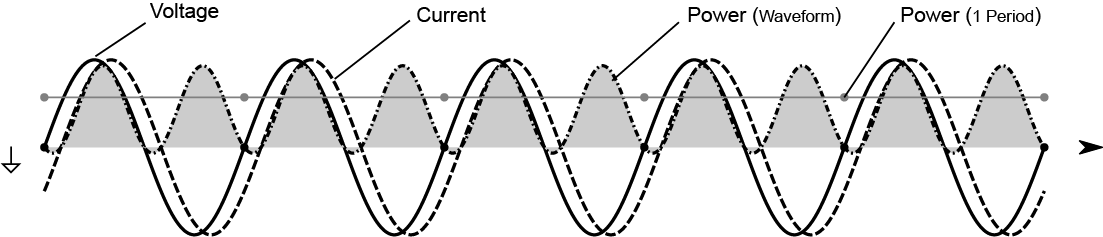
Fig. 37 Period Aggregation on an example with 50 Hz Fundamental (Number of Periods = 10)
In the following Table you will find the number of periods which are used at different fundamental Frequencies:
Fundamental Frequency |
Number of Periods N |
Additional Information |
|---|---|---|
1–4.99 |
1 |
|
5–14.99 |
2 |
|
15–24.99 |
4 |
|
25–34.99 |
6 |
|
35–44.99 |
8 |
|
45–54.99 |
10 |
50 Hz Grid |
55–64.99 |
12 |
60 Hz Grid |
65–74.99 |
14 |
|
… |
… |
… |
The Harmonic Calculation interval will always be linked to N periods but equates to about 200ms of a time window.
This is true for the Harmonics update rate setting “Default”. In case the Harmonics update rate setting is set to “Fast” the time window will half from the “Default” setting to 100 ms. For example in a 50 Hz Grid the “Default” Harmonic output will be after every 10 Periods the “Fast” Harmonic output will be after every 5 Periods, meaning double the output rate of the “Default” Harmonic update rate setting. See more in Settings below.
Settings
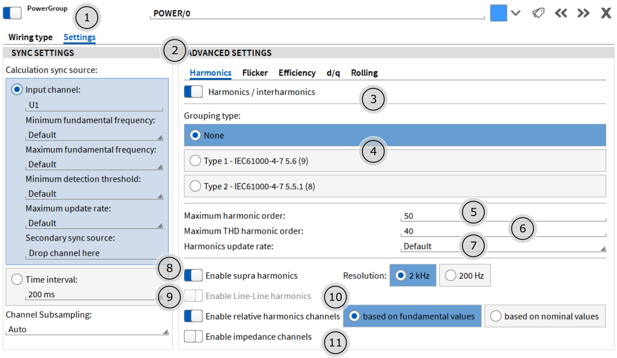
Fig. 38 Harmonic Settings
Power Group’s Tab for Settings
Details Tab for Settings of the Harmonic Analysis
Enable/Disable Harmonic Analysis
Selector for Grouping Type
Input Field for maximum order of Harmonics to be calculated and displayed
Input Field for number of Harmonics in THD calculation (must be lower or equal than (5))
Harmonic update rate, options: “Default” or “Fast”. “Fast” meaning double the output rate of “Default”
Enable/Disable supraharmonic analysis, options: Resolution of 2kHz or 200Hz
Enable/Disable Line-Line harmonics
Enable/Disable relative harmonics channels, options: set relative harmonics channels to be based on fundamental or nominal value
Enable/Disable impedance channels
Harmonic Grouping
Symbol |
Description |
|---|---|
|
RMS Magnitude of FFT-Bin |
|
RMS Magnitude of Harmonic Order h (Grouping “None”) |
|
RMS Magnitude of Harmonic Order h (Grouping “Type 1”) |
|
RMS Magnitude of Harmonic Order h (Grouping “Type 2”) |
|
Number of fundamental Periods |
|
Harmonic Order |


Mode: “None”
When this mode is selected, only the harmonic bins are taken for generation of the harmonic data.
![\begin{aligned}
Y_h &= Y_c[NP \cdot h]
\end{aligned}](../_images/math/cdc3c34c13a21dffd32e592a042b6ae797d91c34.png)
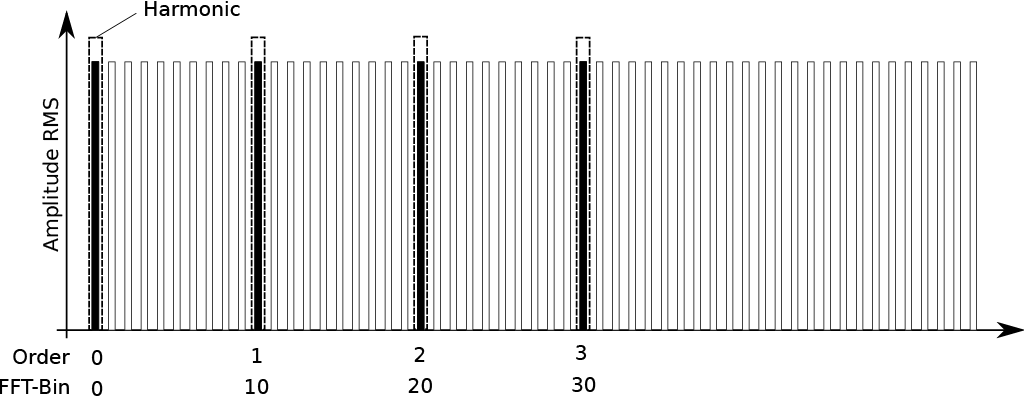
Fig. 39 Grouping Schema Mode “None”
This example shows the grouping for 50 Hz fundamental Frequency.
Mode: “Type 1”
When this mode is selected, the harmonics are grouped according to IEC61000-4-7 Section 5.6.
![\begin{aligned}
Y_{sg,h} &= Y_c[NP \cdot h] & NP < 2 \\
Y_{sg,h} &= \sqrt{\sum_{k=-1}^{1} Y_c \left[ NP \cdot h + k \right]^2} & NP >= 2
\end{aligned}](../_images/math/d71d43fffa4522d450d2aabbc54a5d84671a557b.png)
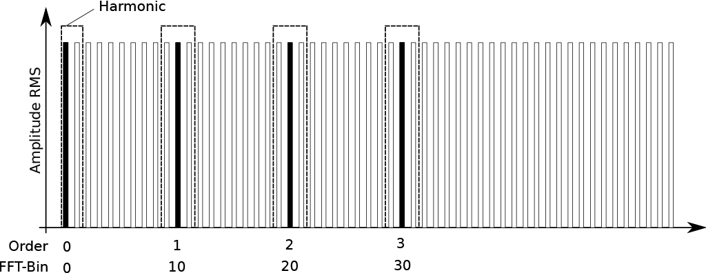
Fig. 40 Grouping Schema Mode “Type 1”
Mode: “Type 2”
When this mode is selected, the harmonics are grouped according to IEC61000-4-7 Section 5.5.1.
![\begin{aligned}
Y_{g,h} &= Y_c[NP \cdot h] & NP < 2 \\
Y_{g,h} &= \sqrt{\frac{1}{2} Y_c \left[NP \cdot h - \frac{N}{2} \right]^2 + \sum_{k=\frac{-N}{2}+1}^{\frac{N}{2}-1} Y_c \left[ NP \cdot h + k \right]^2 + \frac{1}{2} Y_c \left[NP \cdot h + \frac{N}{2} \right]^2} & NP >= 2
\end{aligned}](../_images/math/678faa1c816653848a206da0242191491a32b7c9.png)
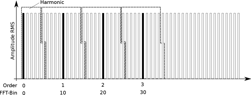
Fig. 41 Grouping Schema Mode “Type 2”
Interharmonic Grouping
Symbol |
Description |
|---|---|
|
RMS Magnitude of FFT-Bin |
|
RMS Magnitude of Interharmonic Order h (Grouping “None”) |
|
RMS Magnitude of Interharmonic Order h (Grouping “Type 1”) |
|
RMS Magnitude of Interharmonic Order h (Grouping “Type 2”) |
|
Number of fundamental Periods |
|
Interharmonic Order |


Mode: “None”
When this mode is selected, all bins (except of harmonic bin) are taken for generation of the interharmonic data.
![\begin{aligned}
Y_{ih} &= NaN & NP = 1 \\
Y_{ih} &= \sqrt{\sum_{k=1}^{N-1} Y_c \left[ NP \cdot h + k \right]^2 } & NP > 1
\end{aligned}](../_images/math/1c860314795d92bb3377ab8712cdda43cfccc1c7.png)
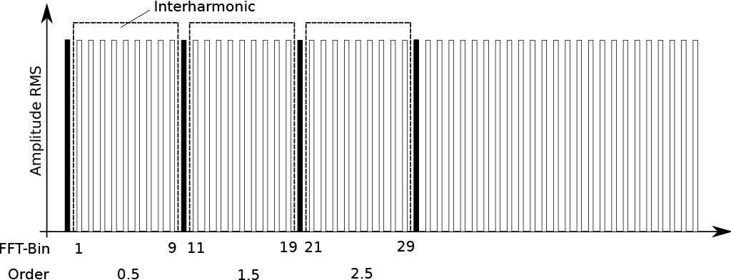
Fig. 42 Grouping Schema Mode ”None”
This example shows the grouping for 50 Hz fundamental Frequency.
Mode: “Type 1”
When this mode is selected, the Interharmonics are grouped according to IEC61000-4-7 Section 5.6.
![\begin{aligned}
Y_{isg,h} &= NaN & NP <= 2 \\
Y_{isg,h} &= \sqrt{\sum_{k=2}^{N-2} Y_c \left[ NP \cdot h + k \right]^2} & NP > 2
\end{aligned}](../_images/math/8c6a3c51979862a22cc40e9b8e0c3ee34d53d4b7.png)
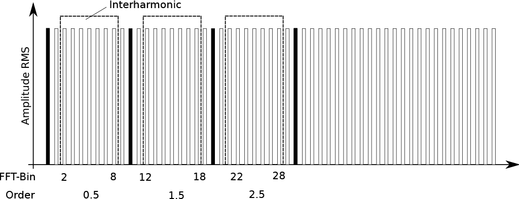
Fig. 43 Grouping Schema Mode “Type 1”
Mode: “Type 2”
When this mode is selected, the Interharmonics are grouped according to IEC61000-4-7 Section 5.5.1.
![\begin{aligned}
Y_{ig,h} &= NaN & NP = 1 \\
Y_{ig,h} &= \sqrt{\sum_{k=1}^{N-1} Y_c \left[ NP \cdot h + k \right]^2} & NP > 1
\end{aligned}](../_images/math/eda05f776448f5baee4e9adda436e11b6e24b654.png)
Fig. 44 Grouping Schema Mode “Type 2”
Higher Frequency Grouping
The Higher Frequency Grouping is orientated on fixed frequency bands (see IEC/EN61000-4-7 Appendix B). It is independent from the fundamental frequency and working between 10 and 1000 Hz.
Symbol |
Description |
|---|---|
|
RMS Magnitude of FFT-Bin |
|
RMS Magnitude of Higher Frequency Order b |


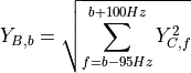
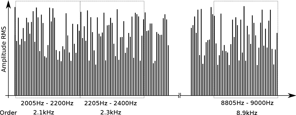
Fig. 45 Higher Frequency Grouping
This example shows the grouping for every fundamental frequency.
Supraharmonics Grouping
Unlike the other grouping methods, the Supraharmonics are aggregated in time. The Supraharmonics calculation will output channels with the Harmonic components in the frequency range between 8kHz and 150kHz.
Since the Line Resolution of 2kHz (or optional 200Hz) is much finer than the Harmonic Calculation Interval meaning the update rate of Supraharmonics is much faster than the Harmonic Interval the output channels will undergo a statistics evaluation (AVG, MIN, MAX). Each Supraharmonic Evaluation will result in 3 Channels with indices  . As an example for the first Voltage:
  .
.
Symbol |
Description |
|---|---|
|
RMS Magnitude of FFT-Bin b |
|
Minimum RMS Magnitude of Supraharmonics order i |
|
Average RMS Magnitude of Supraharmonics order i |
|
Maximum RMS Magnitude of Supraharmonics order i |
|
Number of fundamental periods (10 @ 50 Hz, 12 @ 60 Hz) |
|
Number of Short Time FFTs in time interval of NP |
|
Samplerate |


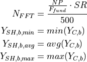
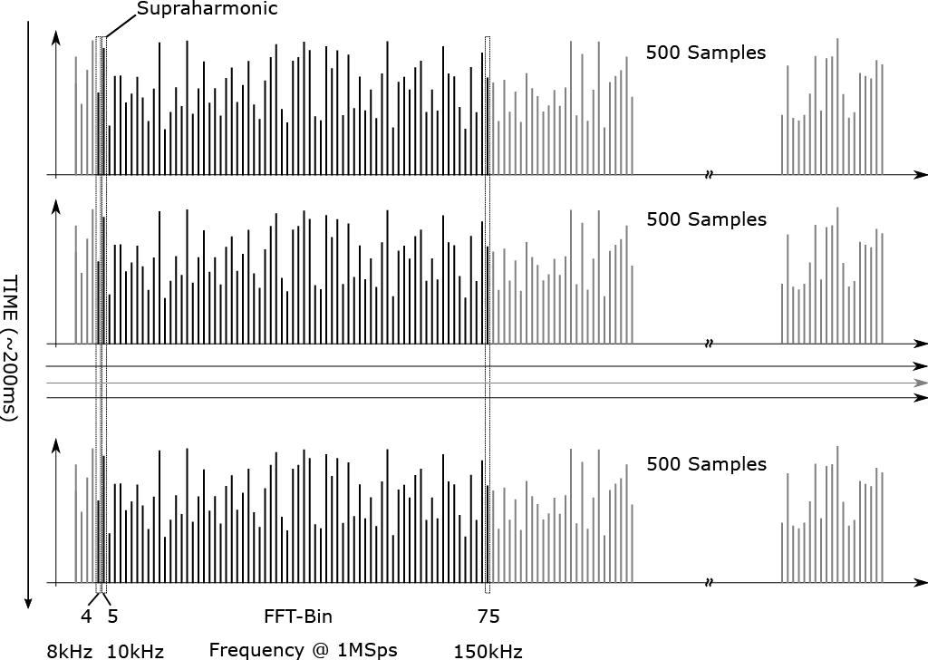
Fig. 46 Supraharmonic Grouping
This graphic shows the time domain aggregation of the short time FFT results. The number of FFTs is orientated on the number of fundamental periods.
In the graphics above the Supraharmonics Resolution is set to the default 2 kHz. In case the option in the Power Group settings is set to 200 Hz the FFT-Bin at 150 kHz will be 750, not 75, and the line resolution will be 200 Hz.
Harmonic Element Extraction
Specific elements from the Harmonic Vector can be extracted as separate channels.
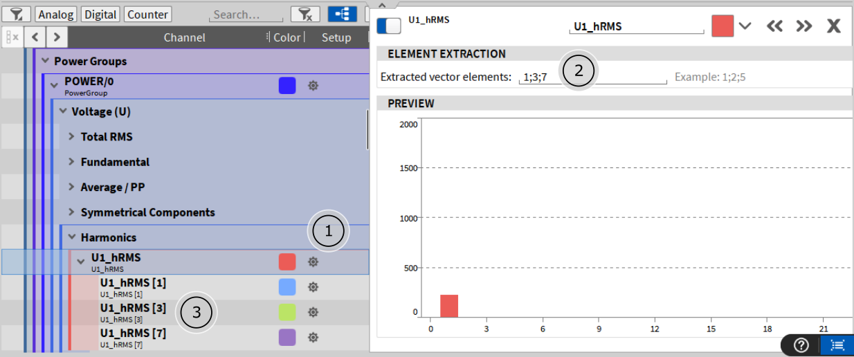
Fig. 47 Harmonic Element Extraction
Open Channel Settings of Harmonic Vector
Select elements starting from zero
Each extracted element will create a new scalar channel under the Harmonic Vector
Voltage Channels (U)
U[i]_h[k]RMS
See Harmonic Grouping.
![\begin{aligned}
Y_c &= abs(\underline{U}[i]_{fft}) \cdot \frac{1}{\sqrt{2}} & \\
U[i]\_h[k]_{RMS} &=
\begin{cases}
Y_h & \quad \text{if } MODE = "None" \\
Y_{sg,h} & \quad \text{if } MODE = "Type 1"\\
Y_{g,h} & \quad \text{if } MODE = "Type 2"\\
\end{cases} & Unit: \textbf{V}
\end{aligned}](../_images/math/4e9c5f62ca0062938ff6a36b6f3105f1f7368d4c.png)
U[i]_h[k]REL
Voltage relative harmonic value, referenced to fundamental. Must be enabled separately.
![\begin{aligned}
U[i]\_h[k]_{REL} &= \frac{U[i]\_h[k]_{RMS}}{U[i]\_h[1]_{RMS}} \cdot 100\% & Unit: \textbf{\%}
\end{aligned}](../_images/math/e604ae2e1c4b22922d7f3405f65792ca250ecd7b.png)
U[ij]_h[k]RMS
Line-to-Line Harmonic Magnitude. Only available in 3-Phase Configurations (3P3W, 3P4W, 2V2A).
![\begin{aligned}
\underline{U}[i]_{h} = U[i]\_h[k]_{RMS} \cdot ( & cos (U[i]\_h[k]_{PHI} \cdot \frac{\pi}{180}) + & \\
& j \cdot sin ( U[i]\_h[k]_{PHI} \cdot \frac{\pi}{180} )) & \\
\underline{U}[12]_{h} &= \underline{U}[1]_{h} - \underline{U}[2]_{h} & \\
\underline{U}[23]_{h} &= \underline{U}[2]_{h} - \underline{U}[3]_{h} & \\
\underline{U}[31]_{h} &= \underline{U}[3]_{h} - \underline{U}[1]_{h} & \\
U[ij]\_h[k]_{RMS} &= abs(\underline{U}[ij]_{h}) & Unit: \textbf{V}
\end{aligned}](../_images/math/35afccbcefbbdd928156c6d365e9a6462851a8f6.png)
U[i]_h[k]PHI
![\begin{aligned}
PHI_{ref} &= arg(\underline{U1}_{fft}[1 \cdot NP]) + 90^\circ & \\
U[i]\_h[k]_{PHI} &= arg(\underline{U}[i]_{fft}[k \cdot NP]) + 90^\circ - k \cdot PHI_{ref} & Unit: \mathbf{deg} (^\circ)
\end{aligned}](../_images/math/f705b4747cc44f89eb8ba48ecd4d7ec3ffa6fd1c.png)
U[i]_ih[k]RMS
![\begin{aligned}
Y_c &= abs(\underline{U}[i]_{fft}) \cdot \frac{1}{\sqrt{2}} & \\
U[i]\_ih[k]_{RMS} &=
\begin{cases}
Y_{ih} & \quad \text{if } MODE = "None" \\
Y_{isg,h} & \quad \text{if } MODE = "Type 1"\\
Y_{ig,h} & \quad \text{if } MODE = "Type 2"\\
\end{cases} & Unit: \textbf{V}
\end{aligned}](../_images/math/874ad725296c4039b1e4d03b92b574e471fc86f8.png)
U[i]_ih[k]REL
Voltage relative interharmonic value, referenced to fundamental. Must be enabled separately.
![\begin{aligned}
U[i]\_ih[k]_{REL} &= \frac{U[i]\_ih[k]_{RMS}}{U[i]\_h[1]_{RMS}} \cdot 100\% & Unit: \textbf{\%}
\end{aligned}](../_images/math/f3a6fe33296f6a4dc5d755b4992c94966dd18980.png)
U[i]_hf[k]RMS
See Higher Frequency Grouping.
![\begin{aligned}
Y_{C} &= abs(\underline{U}[i]_{fft}) \cdot \frac{1}{\sqrt{2}} & \\
U[i]\_hf[k]_{RMS} &= Y_{B,b} & Unit: \textbf{V}
\end{aligned}](../_images/math/8e4cc25c749559189b304df726e4fa7c0eda8d06.png)
U[i]_sh[k]MIN
Minimum Value of Voltage Supraharmonics Grouping. See Supraharmonics Grouping.
![\begin{aligned}
U[i]\_sh[k]_{MIN} &= Y_{SH,b,min} & Unit: \textbf{V}
\end{aligned}](../_images/math/8fb0d2d98b3128f7adba5d1415a134d93d1a6d67.png)
U[i]_sh[k]AVG
Average Value of Voltage Supraharmonics Grouping. See Supraharmonics Grouping.
![\begin{aligned}
U[i]\_sh[k]_{AVG} &= Y_{SH,b,avg} & Unit: \textbf{V}
\end{aligned}](../_images/math/3343fc2b160349b0b4b2148f43e7dc2dbfe3ce14.png)
U[i]_sh[k]MAX
Maximum Value of Voltage Supraharmonics Grouping. See See Supraharmonics Grouping.
![\begin{aligned}
U[i]\_sh[k]_{MAX} &= Y_{SH,b,max} & Unit: \textbf{V}
\end{aligned}](../_images/math/dbc4506480435780ce72c950d52dff9f559d0882.png)
U[i]_THD
Voltage Total Harmonic Distortion, highest used harmonic is  (selectable in menu in the Harmonics tab).
![\begin{aligned}
U[i]_{THD} &= 100 \cdot \sqrt{\sum_{k=2}^{k_{max}} \left( \frac{U[i]_{h[k]RMS}}{U[i]_{h[1]RMS}} \right)^2 } & Unit: \mathbf{\%}
\end{aligned}](../_images/math/6eda6fe8c377073b6404562e08d74b98d440cb85.png)
U[ij]_THD
Line-Line Voltage Total Harmonic Distortion, highest used harmonic is (selectable in menu in the Harmonics tab).
![\begin{aligned}
U[ij]_{THD} &= 100 \cdot \sqrt{\sum_{k=2}^{k_{max}} \left( \frac{U[ij]_{h[k]RMS}}{U[ij]_{h[1]RMS}} \right)^2 } & Unit: \mathbf{\%}
\end{aligned}](../_images/math/759287e1f3869f9c3c817ae216f3b923515b5cc6.png)
U[i]_THV
Total Harmonic Voltage, highest used harmonic is (selectable in menu in the Harmonics tab).
![\begin{aligned}
U[i]_{THV} &= \sqrt{\sum_{k=2}^{k_{max}} \left(U[i]_{h[k]RMS} \right)^2 } & Unit: \mathbf{V}
\end{aligned}](../_images/math/2f4dcec4f93abf2e85534e5c53571ea8bc96c65a.png)
Current Channels (I)
I[i]_h[k]RMS
![\begin{aligned}
Y_c &= abs(\underline{I}[i]_{fft}) \cdot \frac{1}{\sqrt{2}} & \\
I[i]\_h[k]_{RMS} &=
\begin{cases}
Y_h & \quad \text{if } MODE = "None" \\
Y_{sg,h} & \quad \text{if } MODE = "Type 1"\\
Y_{g,h} & \quad \text{if } MODE = "Type 2"\\
\end{cases} & Unit: \textbf{A}
\end{aligned}](../_images/math/b749d2b9fdc739b1b60d56cc52516554bdc7d23c.png)
I[i]_h[k]REL
Current relative harmonic value, referenced to fundamental. Must be enabled separately.
![\begin{aligned}
I[i]\_h[k]_{REL} &= \frac{I[i]\_h[k]_{RMS}}{I[i]\_h[1]_{RMS}} \cdot 100\% & Unit: \textbf{\%}
\end{aligned}](../_images/math/7130667eae5bf64782991ab2cb5d5fba426c8ebe.png)
I[i]_h[k]PHI
![\begin{aligned}
PHI_{ref} &= arg(\underline{U1}_{fft}[1 \cdot NP]) + 90^\circ & \\
I[i]\_h[k]_{PHI} &= arg(\underline{I}[i]_{fft}[k \cdot NP]) + 90^\circ - k \cdot PHI_{ref} & Unit: \mathbf{deg} (^\circ)
\end{aligned}](../_images/math/5e0e2b8cff62ef42714b15dc0f6fabdbe7799a4e.png)
I[i]_ih[k]RMS
![\begin{aligned}
Y_c &= abs(\underline{I}[i]_{fft}) \cdot \frac{1}{\sqrt{2}} & \\
I[i]\_ih[k]_{RMS} &=
\begin{cases}
Y_{ih} & \quad \text{if } MODE = "None" \\
Y_{isg,h} & \quad \text{if } MODE = "Type 1"\\
Y_{ig,h} & \quad \text{if } MODE = "Type 2"\\
\end{cases} & Unit: \textbf{A}
\end{aligned}](../_images/math/c6b5791ecf49045cea45e76eda2e5c5283265961.png)
U[i]_ih[k]REL
Current relative interharmonic value, referenced to fundamental. Must be enabled separately.
![\begin{aligned}
I[i]\_ih[k]_{REL} &= \frac{I[i]\_ih[k]_{RMS}}{I[i]\_h[1]_{RMS}} \cdot 100\% & Unit: \textbf{\%}
\end{aligned}](../_images/math/d0521b11ca643412100b16303334b025ae89e169.png)
I[i]_hf[k]RMS
See Higher Frequency Grouping.
![\begin{aligned}
Y_{C} &= abs(\underline{I}[i]_{fft}) \cdot \frac{1}{\sqrt{2}} & \\
I[i]\_hf[k]_{RMS} &= Y_{B,b} & Unit: \textbf{A}
\end{aligned}](../_images/math/f904d9a558c7b186b68819a1874f5e29b4183848.png)
I[i]_sh[k]MIN
Minimum Value of Current Supraharmonics Grouping. See Supraharmonics Grouping.
![\begin{aligned}
I[i]\_sh[k]_{MIN} &= Y_{SH,b,min} & Unit: \textbf{A}
\end{aligned}](../_images/math/5d7a60bf4f7c94c13e301476fba988f6dd138e44.png)
I[i]_sh[k]AVG
Average Value of Current Supraharmonics Grouping. See Supraharmonics Grouping.
![\begin{aligned}
I[i]\_sh[k]_{AVG} &= Y_{SH,b,avg} & Unit: \textbf{A}
\end{aligned}](../_images/math/19b4b6be21e55d5a296ccd900bef4962c170c811.png)
I[i]_sh[k]MAX
Maximum Value of Current Supraharmonics Grouping. See Supraharmonics Grouping.
![\begin{aligned}
I[i]\_sh[k]_{MAX} &= Y_{SH,b,max} & Unit: \textbf{A}
\end{aligned}](../_images/math/0b99c3163c38db26f6b89e997dffd210f6122d79.png)
I[i]_THD
Current Total Harmonic Distortion, highest used harmonic is (selectable in menu in the Harmonics tab).
![\begin{aligned}
I[i]_{THD} &= 100 \cdot \sqrt{\sum_{k=2}^{k_{max}} \left( \frac{I[i]_{h[k]RMS}}{I[i]_{h[1]RMS}} \right)^2 } & Unit: \mathbf{\%}
\end{aligned}](../_images/math/821c706e2530c0df67540d88362dba0f8344fd1c.png)
I[i]_THC
Current Total Harmonic Current, highest used harmonic is (selectable in menu in the Harmonics tab).
![\begin{aligned}
I[i]_{THC} &= \sqrt{\sum_{k=2}^{k_{max}} \left(I[i]_{h[k]RMS} \right)^2 } & Unit: \mathbf{A}
\end{aligned}](../_images/math/1ca21ebb2c671f14780f67e3d39eec040ee07f4e.png)
Active Power Channels (P)
Grouping Mode always “None”
P[i]_h[k]
Active Power Harmonics.
![\begin{aligned}
P[i]\_h[k] &= U[i]\_h[k]_{RMS} \cdot I[i]\_h[k]_{RMS} \cdot cos \left( U[i]\_h[k]_{PHI} - I[i]\_h[k]_{PHI} \right)& Unit: \mathbf{W}
\end{aligned}](../_images/math/0014ba6e43ab189926e7f248e8282ba899da0646.png)
P[i]_h[k]REL
Relative active Power Harmonics, referenced to fundamental
![\begin{aligned}
P[i]\_h[k]_{REL} &= \frac{P[i]\_h[k]_{RMS}}{P[i]\_h[1]_{RMS}} \cdot 100\% & Unit: \textbf{\%}
\end{aligned}](../_images/math/42667f1d49b7a2ee289f3606ec9d98128fe31170.png)
P[i]_THP
Total Harmonic Power, highest used harmonic is (selectable in menu in the Harmonics tab).
![\begin{aligned}
P[i]_{THP} &= \sum_{k=2}^{k_{max}} P[i]_{h[k]} & Unit: \mathbf{W}
\end{aligned}](../_images/math/b0bd8429804a4245c22f1bc62418ef6c1f310d04.png)
Impedance Channels (RXZ)
R[i]_h
Active Impedance harmonic value. Must be enabled separately.
![\begin{aligned}
R[i]\_h[k] &= \frac{U[i]\_h[k]_{RMS}}{I[i]\_h[k]_{RMS}} \cdot cos \left( U[i]\_h[k]_{PHI} - I[i]\_h[k]_{PHI} \right) & Unit: \textbf{Ohm}
\end{aligned}](../_images/math/a585e290ea1e96d3f9972dbff6acb06ce13ec3a6.png)
X[i]_h
Reactive Impedance harmonic value. Must be enabled separately.
![\begin{aligned}
X[i]\_h[k] &= \frac{U[i]\_h[k]_{RMS}}{I[i]\_h[k]_{RMS}} \cdot sin \left( U[i]\_h[k]_{PHI} - I[i]\_h[k]_{PHI} \right) & Unit: \textbf{Ohm}
\end{aligned}](../_images/math/7691eb4c92e13dbc641668e8be99a9c7ec4e903d.png)
Z[i]_h
Impedance harmonic value. Must be enabled separately.
![\begin{aligned}
Z[i]\_h[k] &= \frac{U[i]\_h[k]_{RMS}}{I[i]\_h[k]_{RMS}} & Unit: \textbf{Ohm}
\end{aligned}](../_images/math/41c9e70bedf5435510bdc06dc743ba5e28185200.png)