Addtional Information
Hardware Specific Settings
This Section covers settings related to the Power Analysis function, which depends on specific hardware components.
Sensor Delay Compensation
Compatible Hardware |
Additional Information |
|---|---|
TRION-1820-POWER-4 |
Since Driver Ver. 3.7 and FW Ver. 55 |
TRION3-1810M-POWER-4 |
Since Driver Ver. 3.7 and FW Ver. 55 |
Current and voltage signals are often not perfectly synchronous due to group delays from the sensors. To compensate this delay (phase shift) between voltage and current input, a new function was added to the Hardware listed in Table 5. This function is also known as Deskew.
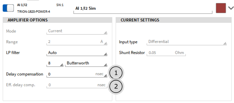
Fig. 34 Delay Compensation Settings: Detail setup (only available for current input)
Input field for target delay compensation in nanoseconds (ns). Allowed range is
 10000ns. Negative values shifts the current backwards in time, positive forward.
Display of effective set delay compensation, the resolution is fixed to 100 ns.
Before adding a compensation value, in this example (Sine Signal with 1 kHz fundamental frequency), the current lags a few degree. This can be seen in the scope as well as in the phase shift of the fundamental:
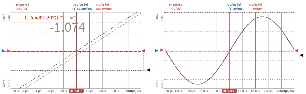
Fig. 35 Delay Compensation Example: Before
After adjusting the value to

the result is now nearly perfect:
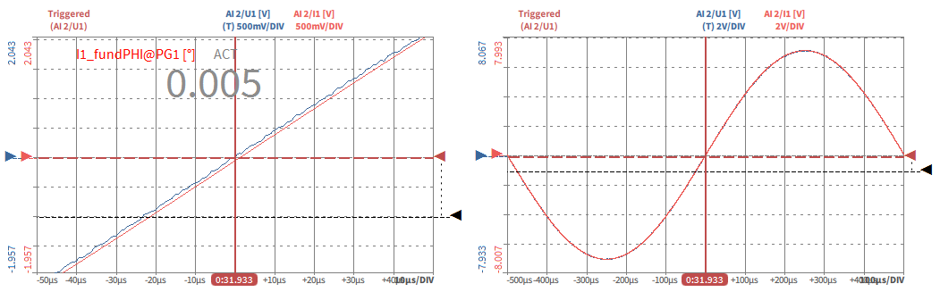
Fig. 36 Delay Compensation Example: After