Understanding Power Analyzer Functions
This chapter contains the basic functionality of OXYGEN Power, its provided measurement capabilities and output channels.
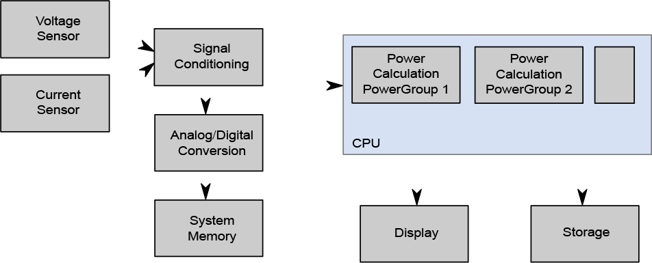
Fig. 11 Signal and Data Flow
Power Analysis in General
Power Analysis basically consists of the following Topics:
Analysis of Voltage and Current Magnitude
Analysis of Active Power
Analysis of Reactive Power
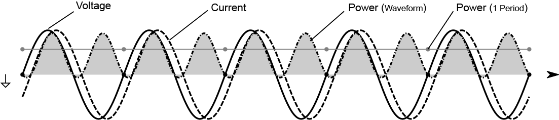
Fig. 12 Power Analysis Basics
Sub-Sampling Settings
To Reduce the calculation load on the measurement device, it is possible to select a subsampling factor. This can be AUTO or a Number between 1 to 5. It reduced the data rate of the input channel by the set factor via skipping algorithm. Only modify if necessary!
Samplerate |
Sub-sampling Factor |
|---|---|
<= 2 MS/s |
1 (= no sub-sampling) |
> 2 MS/s–4 MS/s |
2 |
> 4 MS/s–6 MS/s |
3 |
> 6 MS/s–8 MS/s |
4 |
> 8 MS/s |
5 |
Calculation Modes
The Calculation Cycles depends on the SYNC Source settings. This can be Input Channel (Waveform of the selected channel) or Time Interval (Fixed Interval, available only in DC or Other Wiring Types). The typically operation mode is Input Channel with the first voltage channel (U1).
Interval Mode
This mode is mainly for DC measurements and high fundamental frequencies.
Sync Channel Mode
The Sync Mode is typical for major periodic signals, like rotary field motors or grid connected appliances. In this mode, the calculation of all power output channels is synchronized to the selected channel’s fundamental waveform Zero-Crossings. This guarantees a precise and highly dynamic measurement of all power channels. Most of the power values are updated every single period. The minimum update rate is 0.1 ms but at least 1 fundamental period.
Frequency Measurement
The frequency measurement is done by zero-cross detection. A smart frequency input filter guarantees maximum accuracy, speed and stability.
Samplerate |
Minimum Fundamental |
|---|---|
< 10 kHz |
None |
10 kHz–20 kHz |
0.2 Hz |
20 kHz–1 MHz |
0.2 Hz |
1 MHz–2 MHz |
0.5 Hz |
2 MHz–4 MHz |
1 Hz |
> 5 MHz |
2 Hz |
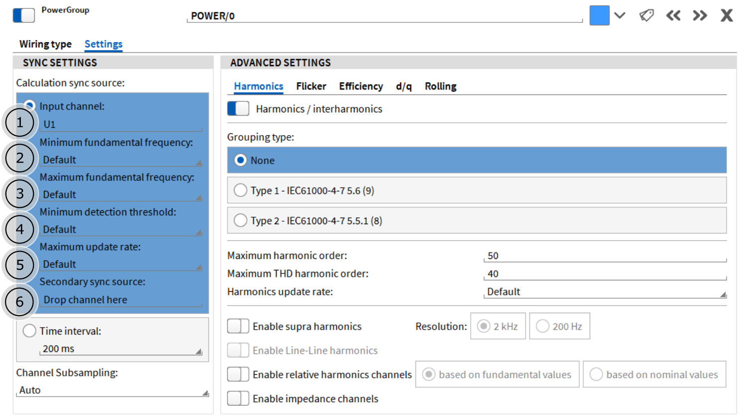
Fig. 13 Expert Settings of Power Group
Synchronisation channel, Drop channel from channel list, Default=First Voltage Channel of Power Group
Minimum fundamental frequency input field (0.2 – f_max)
Maximum fundamental frequency (f_min – 0.1*Samplerate Hz)
Minimum detection threshold (Default / 0.0 % to 50 % of Input Range)
Maximum update rate (Default / 1–5000 ms / 1–100 periods)
Secondary sync source, Drop channel from channel list, Default = Empty
Minimum Fundamental Frequency
This input field holds the setting for the minimum fundamental frequency in Hz which can be measured (lower limit). The following settings are available:
Default: Standard setting, uses 0.2 Hz internally (up to 1 MS/s) and >0.5 Hz above. The actual value is the lower bound of the F_fund channel range.
0.2 .. f_max Hz: User defined setting, the possible range is between Default and 100 Hz.
Maximum Fundamental Frequency
This input field holds the setting for the maximum fundamental frequency in Hz which can be measured (upper limit) The following settings are available:
Default: Standard setting, uses 1500 Hz internally (>20 kS/s). The actual value is the upper bound of the F_fund channel range.
Auto: Uses 1/10 of Samplerate
f_min .. Samplerate/10 Hz: User defined setting, the possible range is between f_min and 1/10 of Samplerate.
Minimum Detection Threshold
This input field holds the setting for the Minimum detection threshold in % of the sync channels input range. The following settings are available:
Default: Standard setting, dynamically adapted to actual fundamental frequency and SNR level
0–50 %: Override setting for Zero Crossing detection threshold in % of range
Maximum Udate Rate
The Maximum update rate is the maximum frequency of the calculated output channels. Input a time interval in millisecond or a number of periods. After entering a number ms or periods can be selected from a dropdown menu.
Default: Standard setting, uses 1 ms internally
1 .. 5000 ms: User defined setting
1 .. 100 periods: User defined setting
SYNC to HARMONIC: Synchronize basic calculation parameters to Harmonic Calculation update rate.
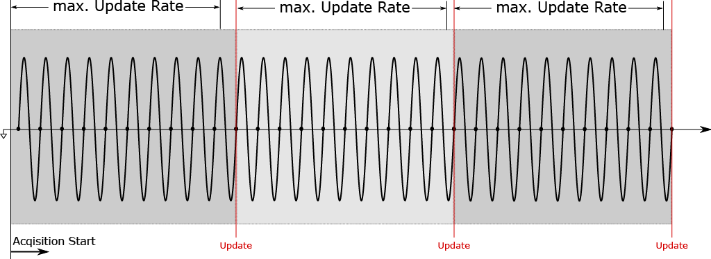
Fig. 14 Update Rate - Example
Secondary Sync Source
The secondary sync source is a fallback channel in case the fundamental frequency in the primary sync source in 1 cannot be detected.
Attention
If the fundamental Frequency value is out of range or the magnitude of the Sync Channel is lower than 0.2 % of the input range, the calculation interval is set to fixed time until the signal is back in range.
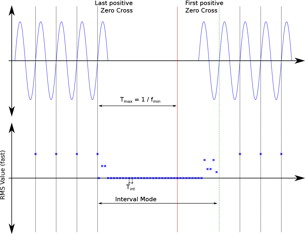
Fig. 15 Calculation Intervals with Gaps
If the distance between two positive Zero Crossings is greater than the maximum detectable fundamental period time, the calculation interval is switched to fixed time base until a full period is detected again.