Software Configuration
This manual only refers to the OXYGEN Order Analysis option. For general software operation instructions, please refer to the latest version of the OXYGEN technical reference manual available on the CCC-portal https://ccc.dewetron.com/ .
Configure Input Channels
Connect sensors for acceleration and angle of rotation
Select settings for the acceleration sensors in th echannel setup (mostly IEPE mode and measuring range)
Setup conuter input for the speed / angle measurement in the channel setup
Remark:
The unit of the rotation angle must be specified in degree [°] and the unit of the running speed must be specified in revolutions per minute[rpm].
Encoder settings
When using an encoder with A, B, Z signals (see Fig. 2 ):
Open detail setup of Main Counter Channel, set Counter Mode to Encoder and enter the number of pulses per revolution
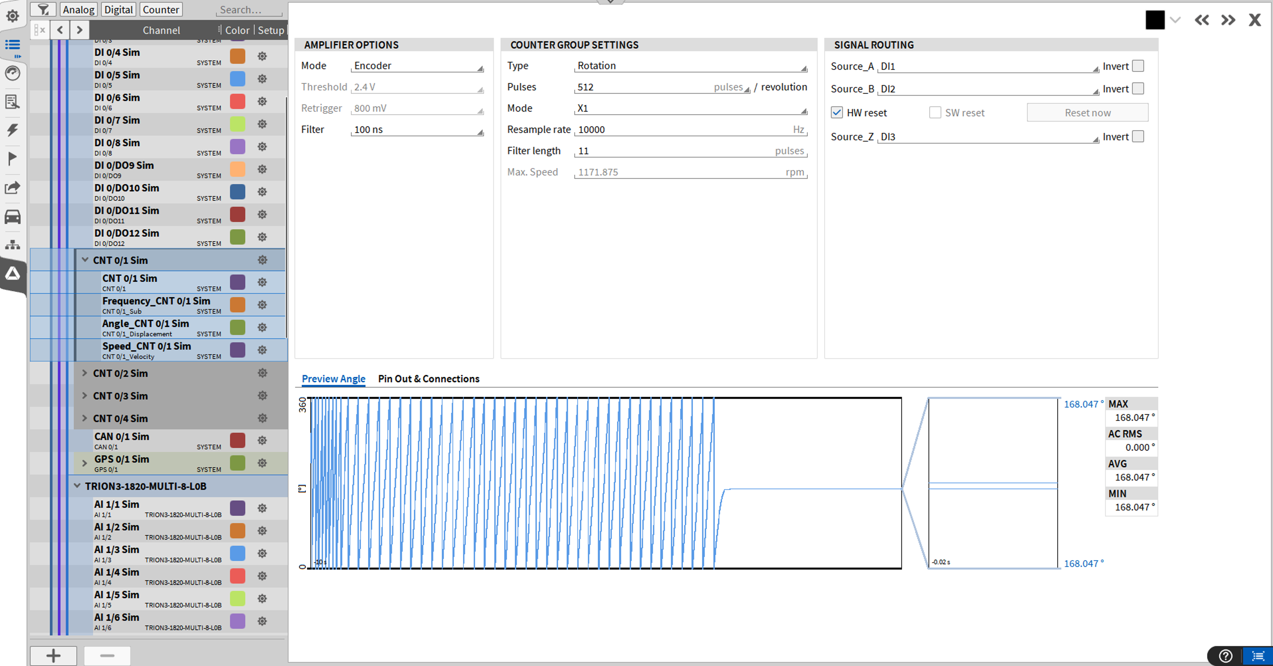
Fig. 2 Counter channel settings or encoder
Tacho settings When using a tacho sensor with a single output (see Fig. 3 ):
Open detail setup of Main Counter Channel, set counter mode to Evrents, enter the number od pulses per revolution and, if necessary, change the Source chsannel. Additionally, check HW-Reset (if available) otherwise use SW-Reset.
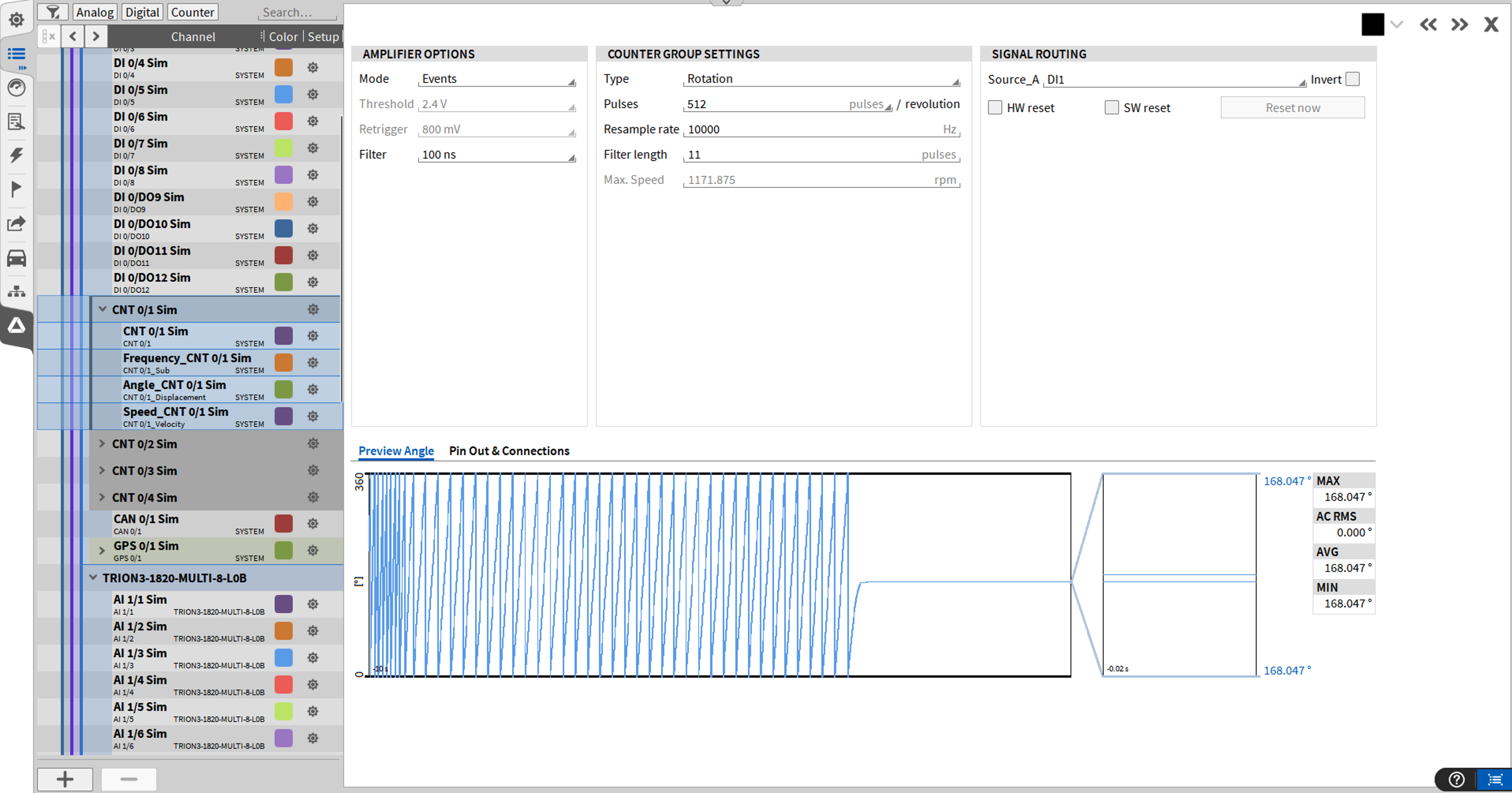
Fig. 3 Counter channel settings for tacho sensors
Sample Rate
Sample rate must be the same for all channels involved in the order analysis. It´s the best to select the counter channels involved (CNT, Frequency, Speed and Angle) plus the along channels to be analyzed and to change their sample rate all together.
The recommendation for a minimum sample rate is:
![\text{Minimum sample rate} =\frac{\text{Maximum speed}[rpm]}{60}*\text{Highest order}*3](../_images/math/3b077876d839c164c36433fe207d5c4ea2926916.png)
Example: 6000 rpm/ 60*100*3 => 30kHz
To change the sample rate, go to the data channels and click on the sample rate (see Fig. 4 )
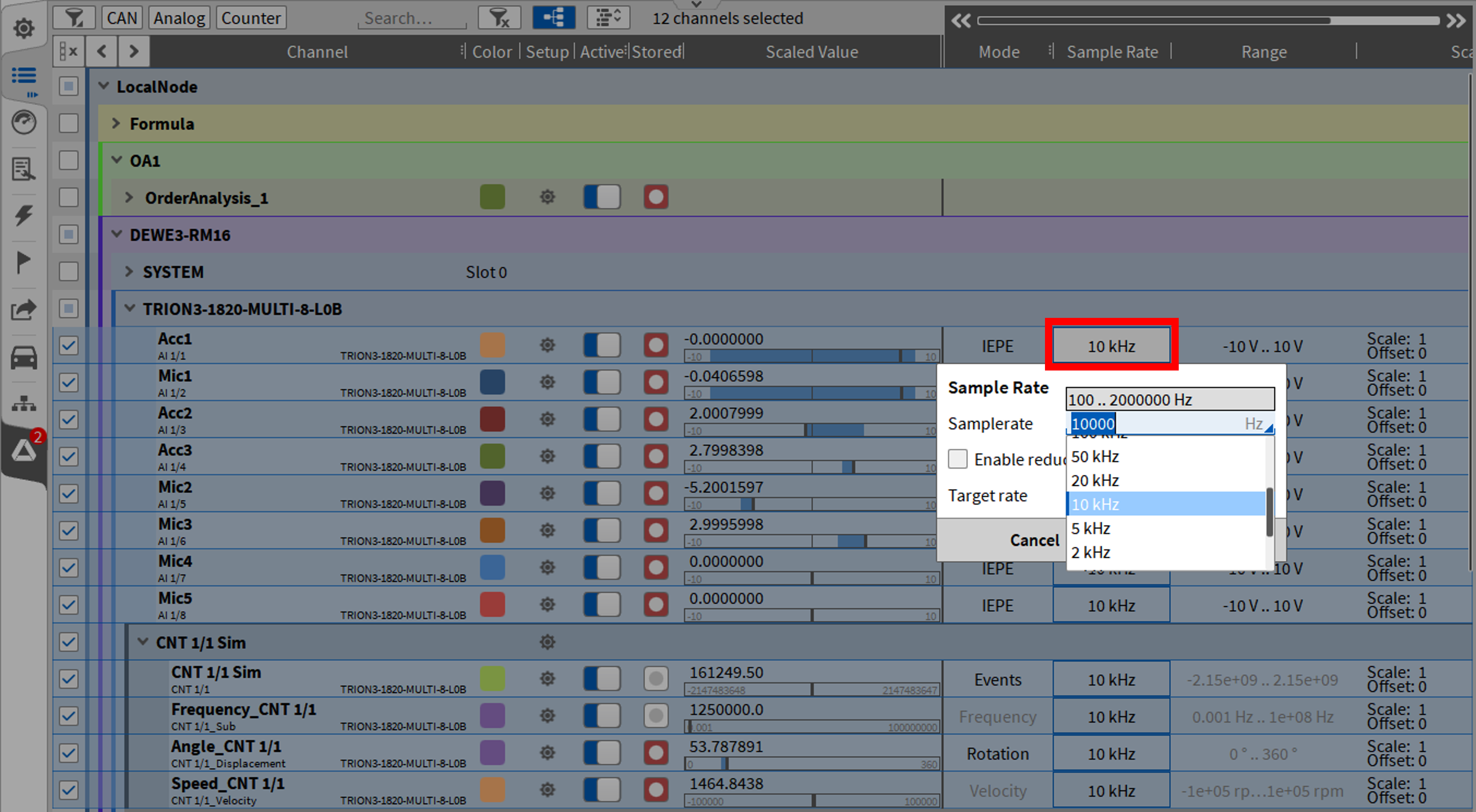
Fig. 4 Setting up te sample rate
Create an Order Analysis Channel
Either create order analysis module without prior selection channels: Press (+), select the Order Anal-ysis module in the Optional Calculations tab. (see Fig. 5 ):
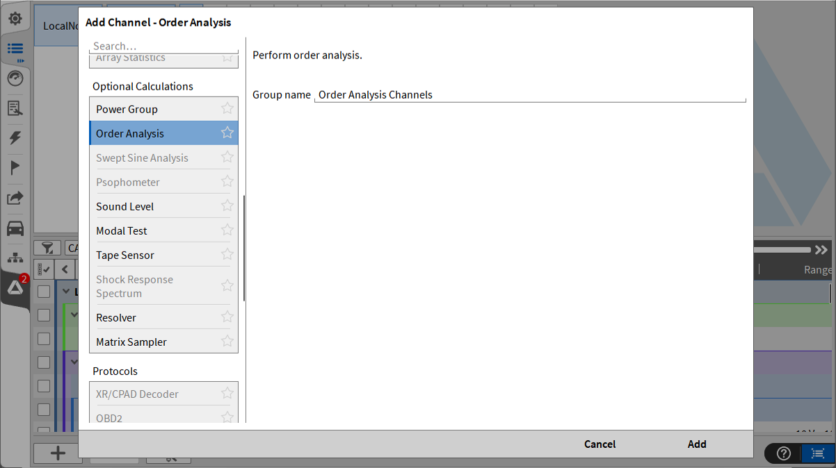
Fig. 5 Creation of Order Analysis module; Option 1
Or create an order analysis module with selection of Speed, Angle and Signal channels:(see Fig. 6 ): Select speed channel -> angle channel -> signal 1…signal n and then press (+) and select the Order Analysis module:
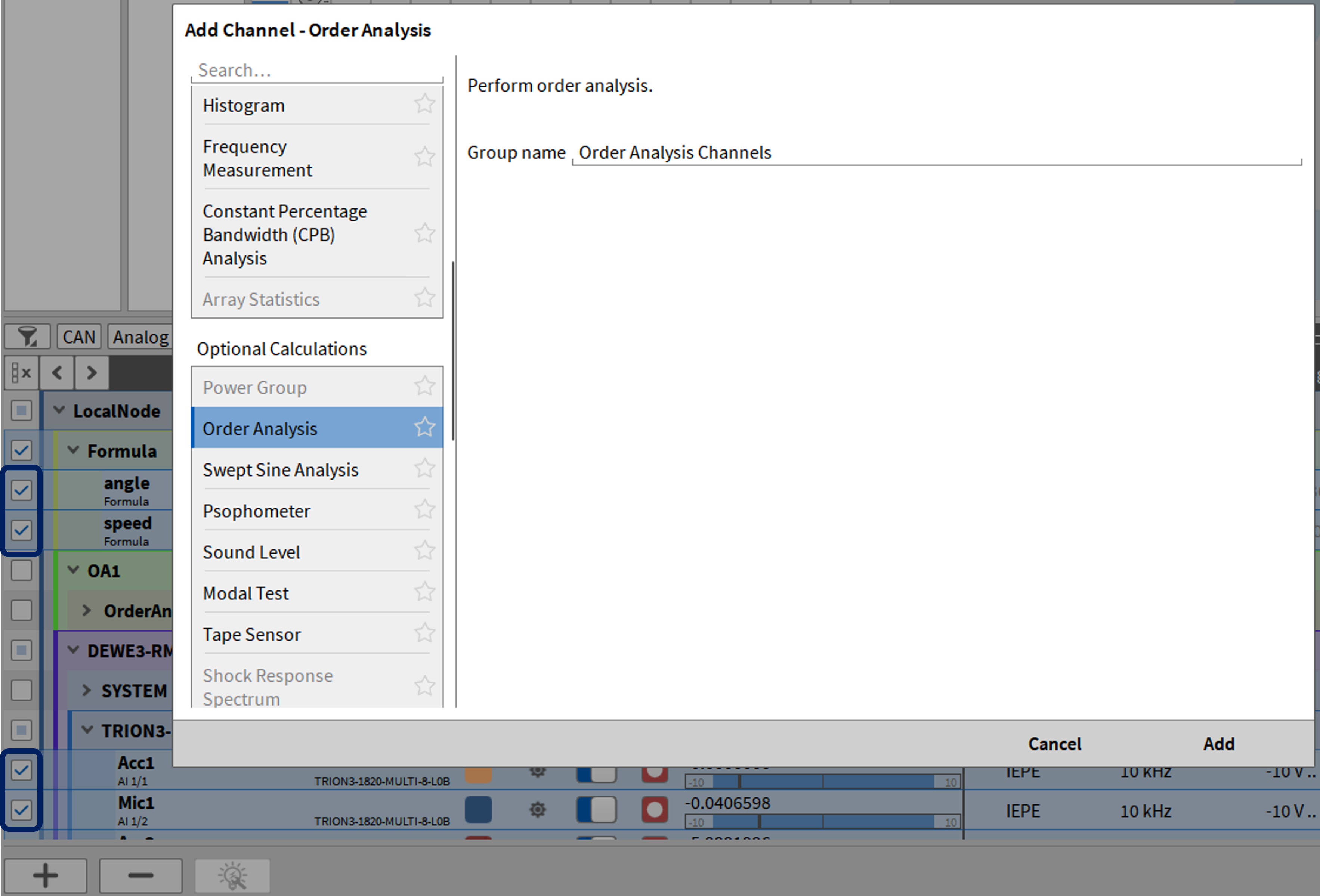
Fig. 6 Creation of Order Analysis module; Option 2
After creating an Order Analysis the default settings can be adjusted to the measurement application: (see Fig. 7 )
Define Group name for one or more order analysis
Select Minimum speed from 60 up to (maximum speed -1)
Set Maximum speed from (minimum speed +1) up to 100.000. Possible range from minimum to maximum speed: 2 decades (i.e. from 100 to 10000 rpm)
Set Speed resolution for the matrix display
Select speed direction:
Both: Update will be performed if speed goes up or down
Down: Update will be performed only if speed goes down
Up: Update will be performed only if speed goes up
Set Order resolution from 0.01 to 1
Set the amplitude type of the order analysis as RMS, Amplitude or Peak-Peak (Up to OXYGEN 7.7 the output of the order analysis was always RMS)
Enter the order to be extracted from the Order Spectrum
Activate Overall RMS value – Calculates the RMS for each input channel over its full order spectrum. The RMS value will be updated for each new input sample:
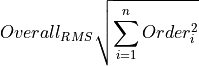
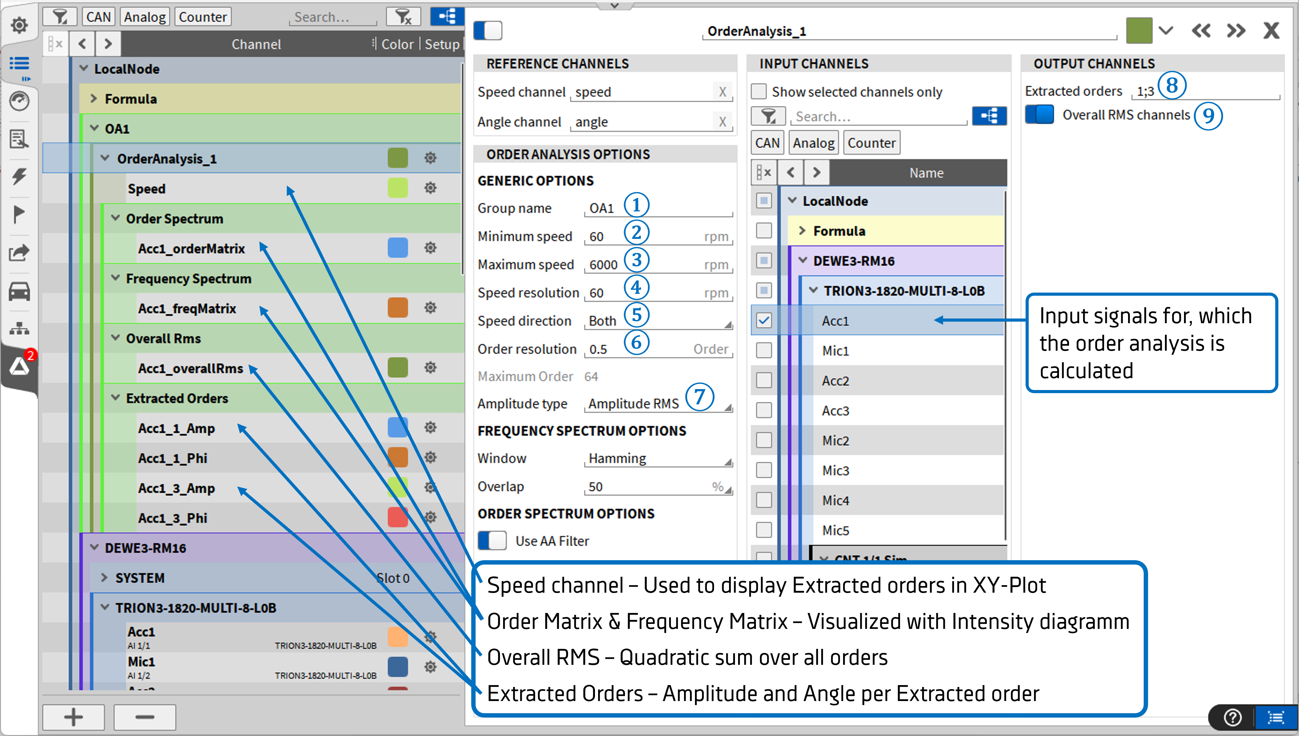
Fig. 7 Order Analysis settings
Note
It is possible to select several signals for which the order analysis should be performed.
Creating a Setup on the Measurement Screen
Drag order matrix channel (= orders over speed) onto the screen (see Fig. 8 )
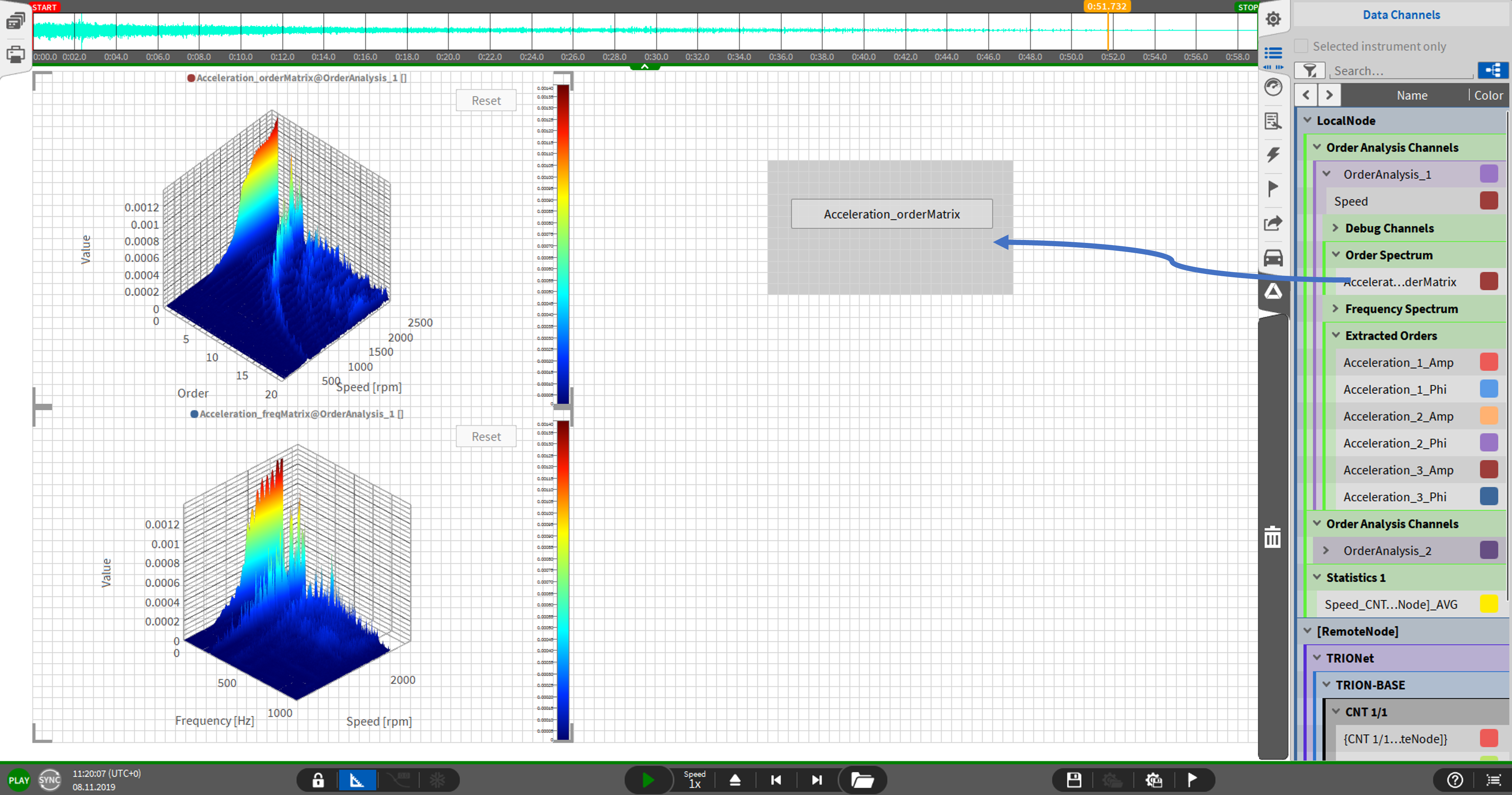
Fig. 8 Display order matrix on the measurement screen
Drag the ferequency matrix channel (=FFT over speed) onto the screen and adjust the instruments (see Fig. 9 )
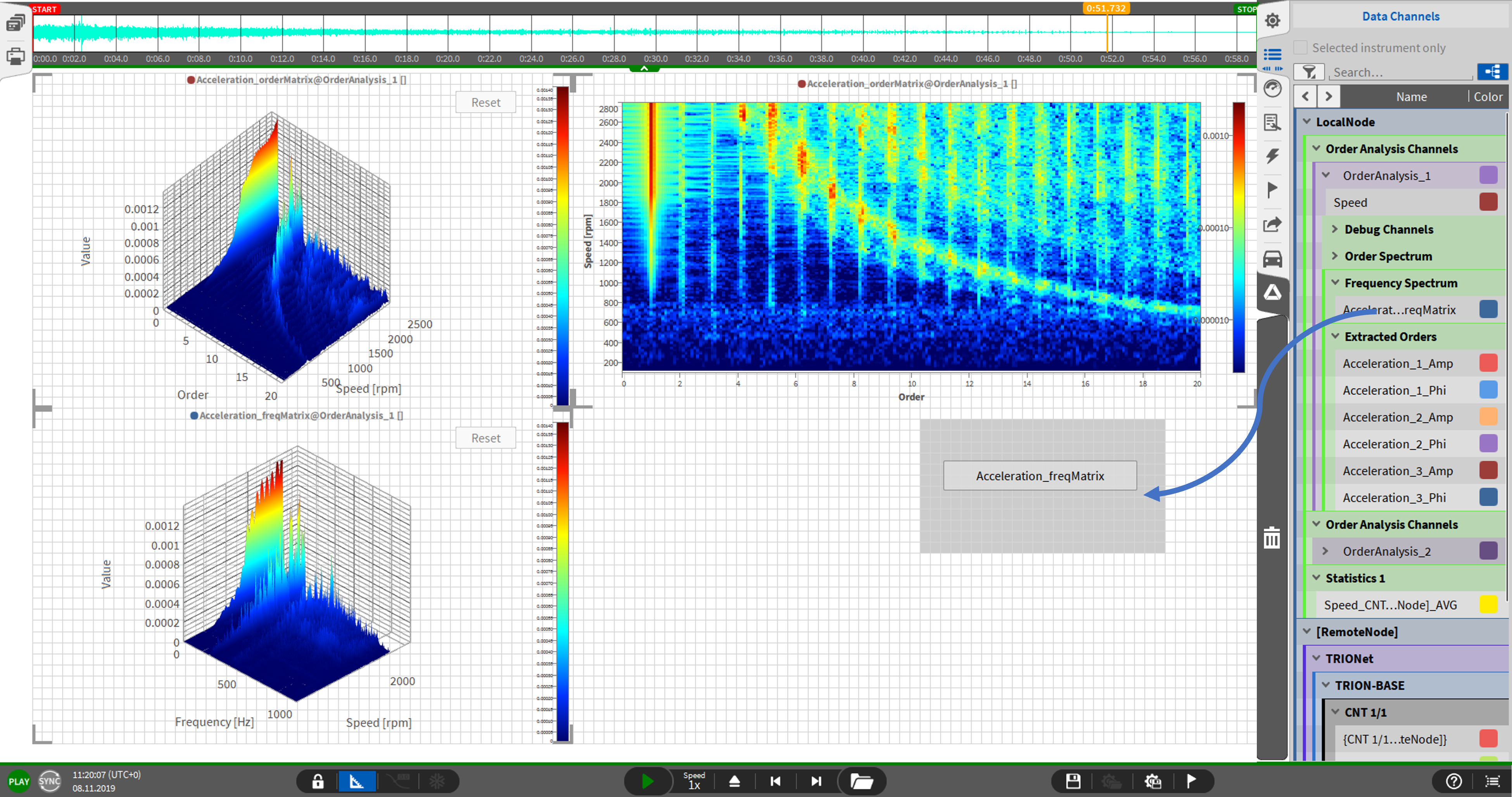
Fig. 9 Display frequency matrix on the measurement screen
If necessary, enable the logarithmic scale (for the color palette) per instrument (see Fig. 10 ).
For enabling the logarithmic scale, the instrument properties must be accessed which is possible by double clicking o the respective instrument.
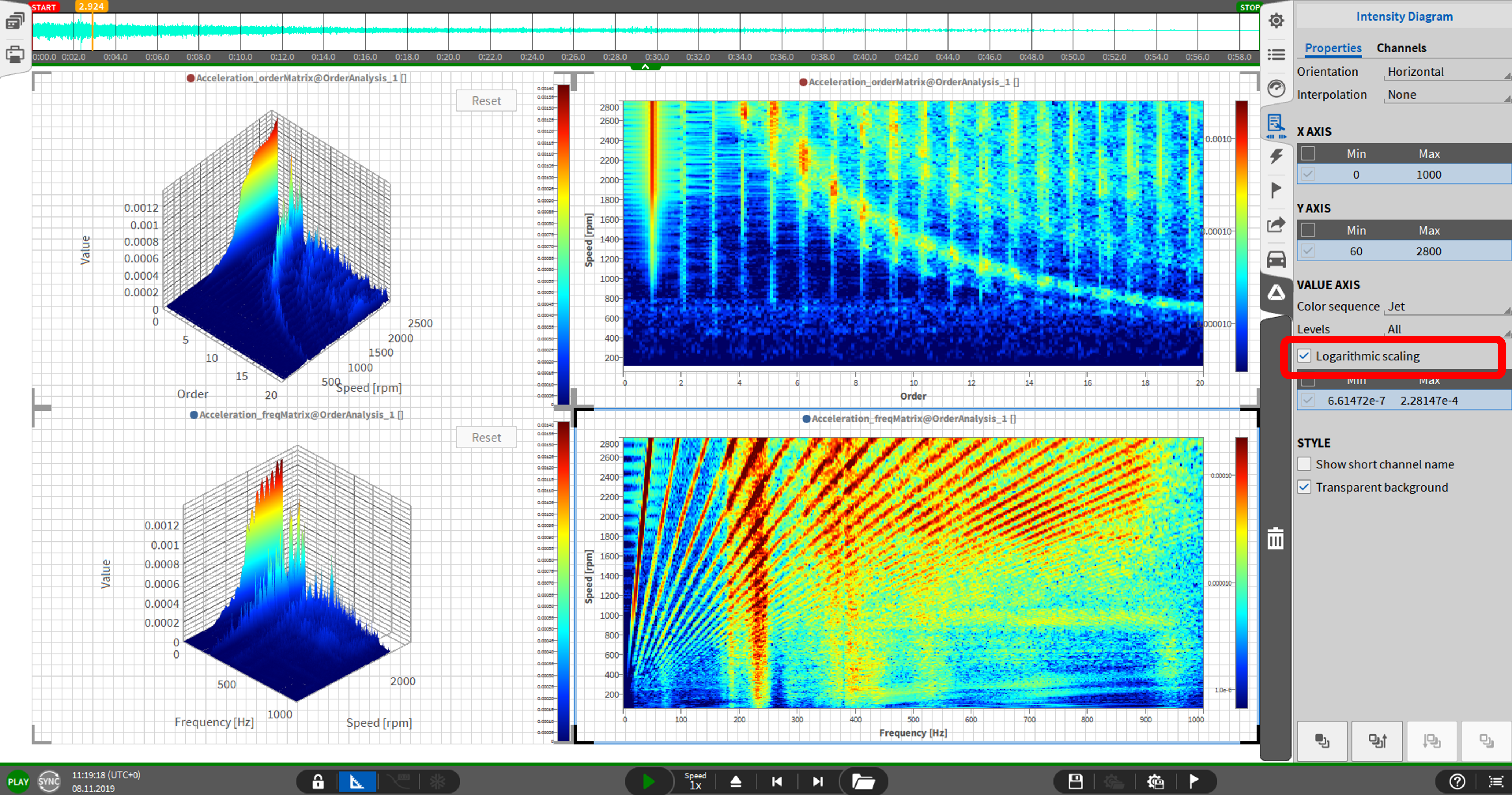
Fig. 10 Logarithmic scaling of the intensity matrix
Optional, add instrument for the current speed (e.g., Speed_CNT 4/1)
Optional, create recorder to display the vakues of the extracted order