Tape Sensor Configuration
This section explains how to use and configure the Tape Sensor Plugin.
A black-and-white tape and an optical sensor connected to a CNT input are required. The gap on the tape needs to be larger than the typical line width of the tape for the gap detection to work properly. This gap can be white or black:
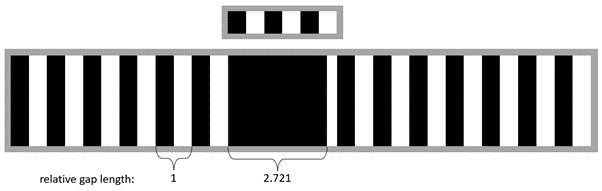
Fig. 1 Setting up the relative gap length
The plugin has an input field called relative gap length. This is set to 2 by default. The relative gap length does not need to be measured or known exactly. However, a minimum relative gap length must be specified in the plugin. For the tape in the figure above specifying a relative gap length of 2 is sufficient. If the relative gap length would be set to 3, then the gap would not be detected.
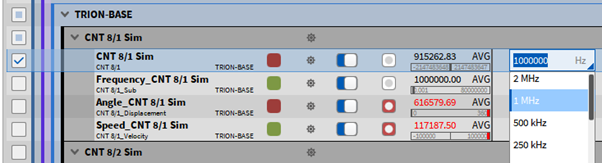
Fig. 2 Changing the sample rate of the counter channel
It is recommended to select a high sample rate for the CNT channel, 1 MHz is recommended. Fig. 2 shows the sample rate input field in the channel list. The sample rate can be changed by clicking this field.
Note that the counter channels CNT, Frequency, Angle and Speed do not need to be recorded. Only the CNT channel is required as the basis for the Tape Sensor calculation. The Angle and Speed channels under CNT 8/1 as seen in Fig. 2 are not the Tape Sensor output channels and can be deactivated.
The Tape Sensor Plugin works online and offline. Offline calculation requires a recorded CNT channel. Note, that CNT channels are not recorded by default.
Adding the Tape Sensor Plugin in OXYGEN is done in the following way:
Start OXYGEN and Open the Channel List (see yellow box in Fig. 3 )
Select one Event counter channel denoted as CNT X/X for which the speed and angle should be calculated by marking the respective check box on the left-hand side (see red box in Fig. 3 )
Click on the + button on the bottom left (see blue box in Fig. 3 )
Click on Tape Sensor in the Advanced Math group (see purple box in Fig. 3 )
Click on the Add button (see green box in Fig. 3 )
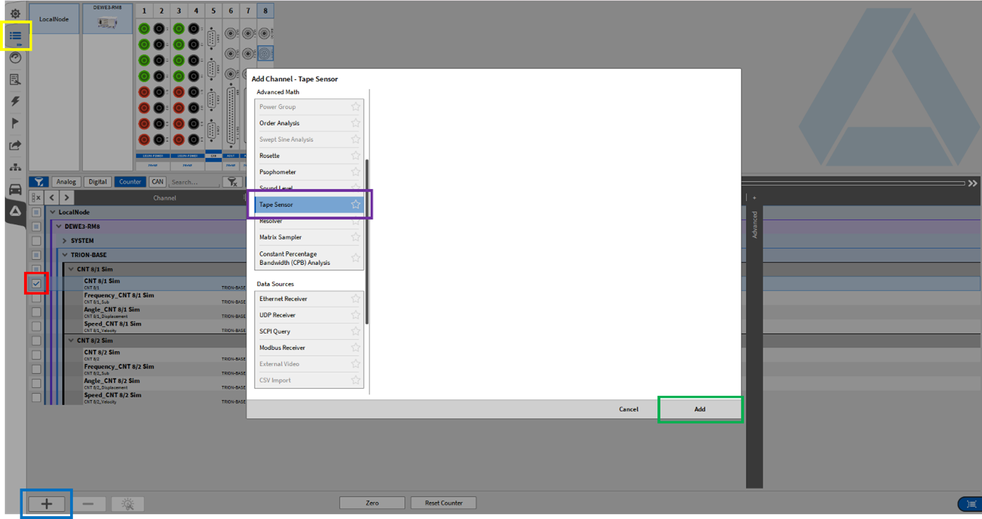
Fig. 3 Adding a Tape Sensor in OXYGEN
The following output channels are available for the Tape Sensor:
Angle, in degrees [0°, 360°]
Speed, in rpm
Pulses per rotation, as float [e.g. 148.685]
Rel gap width, as float [e.g. 2.721]
The angle channel is reset at the end of every gap.
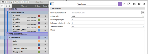
Fig. 4 Tape Sensor settings
The Tape Sensor Plugin has the following properties:
Input counter channel
Output rate, default: 1000 Hz
Relative gap length, default: 2
Pulses per rotation (0 = auto), default: 0
Standstill-Timeout, default 0.1 s
Filter length, centered moving-average filter of angle increments
Status
The Input counter channel should be the event counter, e.g. CNT 8/1. This channel can be selected before or after adding the Tape Sensor. The Output rate can be set in Hz.
The Pulses per rotation are the virtual number of pulses if the gap would include pulses. The default value is 0. So the pulses per rotation are calculated for each rotation. In the automatic mode the pulses per rotation are calculated every rotation and the calculated value is output in the Pulses per rotation channel. This value can be fixed by inputting a user-defined value, like 148.685. This user-defined value can be calculated by using an average of the Pulses per rotation channel over a long period of time at constant speed. This eliminates any inconsistencies of the per revolution calculated value.
The Standstill Timeout is the time needed after no pulse is detected and standstill is assumed. The angle value is held and the speed is set to 0.
In the automatic mode (Pulses per rotation set to 0) two consecutive gaps are required until the speed and angle are updated. Until all pulse information between two gaps has been collected by the counter no speed values can be known, hence the Tape Sensor output channels are NaN (not a number). This is not needed after specifying a user-defined Pulses per rotation value.
The Status field displays errors and warnings. This includes messages like Input channel is not supported or Input channel is not usable.
It is possible to use an analog channel as the Input counter channel, as the plugin recognizes events if the signal increases by at least 0.5 compared to the previous sample. This is intended for CNT channels, counting the TTL signal edges and outputting integer values, but also works for analog chan-nels. If a noisy analog channel is used as the tape sensor input, use a formula channel with the edge() function, available in the formula channel. The edge() function is recommended, since oscillations around 0.5 due to noise will result in wrongly detected events and incorrect calculated speed.