ETHERNET SENDER CONFIGURATION
This manual only describes the Ethernet Sender Plugin. For general software operation instructions, please refer to the latest version of the OXYGEN technical reference manual available on the CCC-portal (https://ccc.dewetron.com/ ).
Start OXYGEN and open the Channel List (see yellow box in Fig. 2)
Select the channels to be transferred via UDP by marking the corresponding checkbox on the left hand side (see orange box in Fig. 2 )
Click on the + button (see blue box in Fig. 2)
Click on Ethernet Sender in the Data Transfer group (see pirple box in Fig. 2)
Click on the Add button (see green box in Fig. 2)
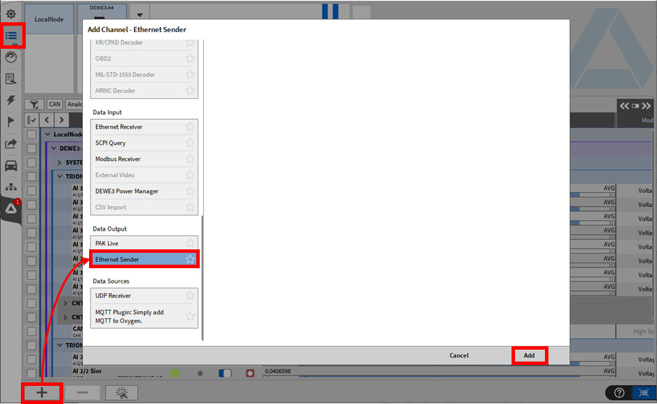
Fig. 2 Adding an Ethernet Sender to OXYGEN
An ETHERNET_SENDER Channels section including the just created Ethernet Sender will be added to the Channel List (See Fig. 3)

Fig. 3 Ethernet Sender added to the Channel List
The name of the Ethernet Sender can be changed as required by double clicking on the name
A click on the Setup button (see red box in Fig. 3 ) will open the Ethernet Sender settings (see Fig. 4 )
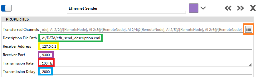
Fig. 4 Editing the Ethernet sender settings
The channels to be transferred can be modified by clicking the button to the right of the Transferred Channels field. (see orange box in Fig. 4 ). After clicking, a popup will open a list containing all channels that can be transferred.
Remarks - If the channel configuration is changed, the xml-file will be updated autpomatically right afterwards. Thus, the xml-file must be reloaded to the receiver device. - Only numerial time-domain channels (i.e. analog input channels or power chnnels) can be transferred but no vector (i.e. an FFT channel) or matrix (i.e. an order spectrum) channels.
The location where the xml-file is stored to is defined in the Description File Path section (see green box in Fig. 4 ). The file path and file name can be freely defined. The xml-file contains the information required to decode the UDP data on the receiver side and must be loaded into the receiver device. The xml-file includes the following information:
UDP port
Timestamp/synchronization information
Channels to be transferred (incl. min/max range, byte offset, bit length and data type)
The IP addres of the ethernet data receiver (device on which the data is decoded), must be specified in the Receiver Address section (see yellow box in Fig. 4 ).
Remarks: If data shall be sent to and decoded on several devices, the IP addresses of all receiver devices must be in the same subnet range and the Receiver Address must be set to xxx.xxx.xxx.25 which denotes a data broadcast address.
The UDP port can be specified in the Receiver Port section (see purple box in Fig. 4 ).
- Remarks:
Make sure that the UDP port is set to 9300 or higher as the ports below might not be available for data transfer.
If the UDP port is changed, the xml-file will be updated automatically right afterwards. Thus, the xml-file must be reloaded to the receiver device.
The transmission rate (data output rate) can be set from 1 to 100 Hz (see red box in Fig. 4 ).
The data Transmission Delay (data output delay) can be set up to 2000 ms (seeb lue box in Fig. 4 ).